background image

b.

If the fold is a

down

fold, the next page printed is a front-facing page.

2.

If the fold direction is the way you want

, do the following to start or continue

a print job:

a.

If necessary, select

Next is Back

. The message on the panel changes to

Next

is Back

, and the

Next is Back

button is grayed out. Selecting the

Next is

Front

button changes the message and the buttons back to what they were

originally.

b.

Select

Close

.

3.

If the fold direction is not the way you want

, do the following to start or

continue a print job:

a.

Advance the forms by one page by using one of the following methods:

v

On the printer operator panel or the Align Forms panel, select

NPRO

.

v

From the touch panel, select

Forms

Advance Paper (NPRO)

and select

Advance One Page

.

b.

If necessary, select

Next is Back

to set the panel message text to agree with

the fold direction. The message on the panel changes to

Next is Back

. The

Next is Back

button is grayed out.

c.

Select

Close

.

Checking forms alignment

About this task

Do this procedure to check forms alignment. Do this procedure when you see a

CHECK FORMS ALIGNMENT

message or whenever you load, splice, or adjust forms.

Procedure:

Procedure

1.

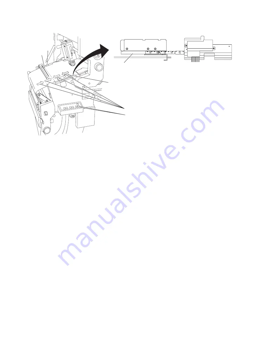
At the lower transfer station tractors, ensure that the forms perforation

(1)

is

aligned with the correct forms length on the tractor scale

(4)

.

c0tu019

1

5

5

4

2

3

Figure 81. Forms fold at the alignment guide

188

Operating the InfoPrint 4100

Содержание InfoPrint 4100 TD3

Страница 1: ...Operating the InfoPrint 4100 InfoPrint 4100 Models TS2 TD3 4 TS3 and TD5 6 S550 1298 02...

Страница 2: ......

Страница 3: ...Operating the InfoPrint 4100 InfoPrint 4100 Models TS2 TD3 4 TS3 and TD5 6 S550 1298 02...

Страница 4: ...and commercial computer software documentation developed exclusively at private expense As specified in Federal Acquisition Regulation 12 212 in the case of civilian agencies and Defense Federal Acqui...

Страница 5: ...operator alert assembly 54 Adjusting the touch panel 55 Reporting printer usage 56 Switching printer modes and printer speed 58 Switching from Duplex to Dual Simplex mode 58 Switching from Dual Simpl...

Страница 6: ...ging the toner collector bag 284 Changing the developer mix 289 Checking the fine filter 299 Changing the fine filter 300 Cleaning the UFC sensor 304 Cleaning the early drum jam sensor 305 Cleaning th...

Страница 7: ...e 414 Forms Identification Bar Code feature FC 4464 417 Adding or changing a form bar code for an existing Snapshot 418 Defining a form bar code for a new Snapshot 419 Loading preprinted bar code form...

Страница 8: ...vi Operating the InfoPrint 4100...

Страница 9: ...nclude common sense measures such as keeping potentially combustible materials for example curtains and chemicals away from the printer providing adequate ventilation and cooling limiting unattended o...

Страница 10: ...ing driving or operating section during operation CAUT0912 Power off the printer and allow the dryer rollers to cool before you start this procedure CAUT0913 CAUTION 5 High voltage is present Use care...

Страница 11: ...27 Laser radiation is present Do not stare into the beam DANGER DANG0914 The Ricoh supplies web page contains links to the material safety data sheets for supplies Safety and environmental notices ix...

Страница 12: ...x Operating the InfoPrint 4100...

Страница 13: ...orms Align Forms displays the Align Forms panel v Words that identify switches indicators levers or tab names appear in bold print For example Press the Start key Select the Printer Definition tab on...

Страница 14: ...xii Operating the InfoPrint 4100...

Страница 15: ...The Printer 2 control unit which includes Operator alert area Touch panel Mouse Keyboard Power control panel The Printer 1 control unit which includes Operator alert area Power control panel v Printer...

Страница 16: ...eral forms path when a printer is used for simplex printing and is using boxed fan fold forms 1 Tractors 2 Transfer station 3 Printhead 4 Toner 5 Developer 6 Power supply 7 Forms input area 8 Forms ex...

Страница 17: ...move up through the forms input area v At Printer 2 the forms enter from the right under the printer through the urge unit in the forms input area They then move up through the forms input area If a...

Страница 18: ...eived from the host Green None Stop was pressed In diagnostic mode Offline printing The system was made not ready by the operator or CE The system cannot print data from the host All safety interlocks...

Страница 19: ...d Configuration Guide for more information Note The supported USB flash memory device is Feature Code 4660 USB Flash Memory Device About the power control panel On Printer 1 the power control panel pr...

Страница 20: ...ol unit frame when the Control Unit Local Remote switch is set to Local Printer Power On Switch Powers on the printer when the Printer Local Remote switch is set to Local Control Unit Power Off If In...

Страница 21: ...or panel duplicate some system controls available on the touch panels In Dual Simplex mode the function keys let you control the printer on which the operator panel is mounted In Duplex mode the funct...

Страница 22: ...u mode the display area lists tasks that require an operator response You can use these menu function keys instead of the equivalent key on the touch panels The tasks displayed depend on the state of...

Страница 23: ...de This key can be selected multiple times each press causes one page to feed You can also use this key to move forms forward to the next top of form position NPRO page This key is active when the pan...

Страница 24: ...This key is active when the panel is in Status mode or Menu mode About the indicators Indicators on the printer operator panel communicate status from the printer This Indicator On Means That Power Th...

Страница 25: ...through the toner hopper 4 in the developer area Table 2 describes the controls on the customer changeable developer Table 2 Developer controls Selecting This Control Does This Developer Mix Inlet 1 A...

Страница 26: ...e printer at the forms input area The developer mix drain hose is also in the forms input area not shown Transfer station area In the transfer station area print images are transferred from the photoc...

Страница 27: ...gate 7 Splicing table 8 Lower tractor covers 9 Tension arm About the printer control panel The printer control panel is just below the transfer station Table 3 on page 14 describes the controls on th...

Страница 28: ...ng Note Use this control only for fan fold forms stacked at the printer stacker If the control is not set correctly the stacker jams Forms Set Down Fold R4CO0102 This control is not active on InfoPrin...

Страница 29: ...rrect position Toner Mark Toner Mark IC3U0031 Allows you to reset errors that occur while aligning tractorless forms About the splicing table Note The Splicing Table is not available on all models The...

Страница 30: ...and forms on the splicing table When the splice lever is down no vacuum is present on the splicing table Tape Slot 4 Holds splicing tape in place during splicing When the splice lever is down the spli...

Страница 31: ...trol Knob Narrower 2 R4CO0116 Changes the distance between the front and rear tractors both upper and lower pairs When the knob is turned counterclockwise the rear tractor moves closer to the front tr...

Страница 32: ...ed Transfer Station Gap Lever Enhanced Commercial Print mode c0tu010 Enables the transfer station to use Enhanced Commercial Print media Use the Transfer Station Control Lever to open the Transfer Sta...

Страница 33: ...and to the right to support the Standard mode About the vacuum stack height lift pin lever and puller controls The Vacuum push button 4 the Vacuum off warning indicator 5 the Puller lever 6 the Puller...

Страница 34: ...off Puller Lever Release 6 R4CO0114 Releases pressure on the scuff and backup rollers inside the fuser area To release these rollers move and hold the puller lever to the release position Puller Lever...

Страница 35: ...on To empty the Paper Dust Collector Box 1 Remove the two screws 1 on the cover plate 2 Remove the box 3 Dispose of the paper dust in the box 4 Reinstall the box 5 Reinstall the two screws Lift Pin Le...

Страница 36: ...on 2 10mm position 1 Printer 2 dual simplex both 3mm position 2 0mm position 3 Simplex 3mm position 2 0mm position 3 About the fuser entry area After the forms receive print images they pass through t...

Страница 37: ...it area The printed and fused forms leave the fuser area and exit at the forms exit area where they go into a postprocessing device or if installed on InfoPrint Models a stacker 2 1 2 50 Hz Printer 60...

Страница 38: ...rea The pendulum is inside the stacker area above the stacker table The swinging of the pendulum helps forms to refold correctly The stacker control panel which is just above the stacker contains cont...

Страница 39: ...on the stacker control panel displays the current form length and lets you adjust it The following illustration shows a forms length setting of 8 2 3 Note When a stacker is not installed you must stil...

Страница 40: ...OP STOP 7 0 1 3 1 2 2 3 8 FORMS LENGTH TABLE READY 18 17 16 15 14 13 12 11 19 FORMS WIDTH 10 9 8 9 10 11 12 13 14 15 16 17 Figure 19 Stacker control panel on InfoPrint 4100 Models TS3 and TD5 6 26 Ope...

Страница 41: ...lets you adjust it On InfoPrint 4100 with the stacker installed this control increases or decreases the stacker forms length setting Figure 20 shows a forms length setting of 8 2 3 To use the stacker...

Страница 42: ...lled this control stops the stacker DOWN R4CO0105 This control is not active on InfoPrint 4100 models TS3 and TD5 6 On InfoPrint Models with the stacker installed this control moves the stacker table...

Страница 43: ...he preprocessing and postprocessing device interface cable connection area 1 is behind the rear cover of either of the control unit frames About the power control panel The following figure shows a po...

Страница 44: ...se of an emergency Do not use Unit Emergency Power Off switch to power off the system unless you have an emergency Doing so can cause loss of data and hardware problems in the control unit attached to...

Страница 45: ...about the printing system tabs for viewing additional information and selecting other tasks and buttons for operating the system The touch sensitive interface allows you to touch a button tab or graph...

Страница 46: ...e Select the Alt F4 key to close the Help window Note Some of the printer console panels appear only for user IDs that have Administrator authority level Administrator panels are indicated with the fo...

Страница 47: ...the Main touch panel on the operator console Figure 25 on page 34 shows the locations of the tabs buttons Status area Current Settings area and Operator Messages area 9 56 6 28 11 Figure 24 Align Form...

Страница 48: ...access to the major task panels which allow you to perform operations on the printer The Frequent Tasks tab provides panels for doing tasks that must be done frequently These include v Snapshots pane...

Страница 49: ...ice only Adapter Mechanism Pre Postprocessors Print Quality Mode v Logs panels Service only Preventative Maintenance Error Log The Printer Definition tab provides panels for setting or changing printe...

Страница 50: ...on displays the Print Registration panel Forms Print Registration Areas on the Main touch panel Table 7 describes the areas on the Main touch panel that provide printer status current printer settings...

Страница 51: ...dicates that the monitor is powered off Note v The on screen display will only display if the monitor is driven by an active video signal v Using this control does not affect power to the printer Brig...

Страница 52: ...the previous menu window or exit the OSD main window On screen display OSD controls The on screen display OSD controls allow you to make adjustments to the image on the touch panel Press both the plu...

Страница 53: ...wn Sub menus v H Position v V Position v Clock v Phase v Memory Recall v Auto Color v Exit OSD Setting OSD Changes the position of the OSD on the touch panel Sub menus v OSD H Position v OSD V Positio...

Страница 54: ...on Provides information about the monitor Sub menus v Horizontal Refresh Rate v Vertical Refresh Rate v Version v Date EXIT EXIT Exit the OSD main window and save your settings 40 Operating the InfoPr...

Страница 55: ...Servicing the printer on page 255 Define forms and load forms At start of job Chapter 4 Working with Snapshots on page 61 Loading forms on page 69 Thread forms Duplex mode ensure proper form alignment...

Страница 56: ...ing the buffer flipper unit on page 274 Clean the Buffer Flipper Unit rollers Once each week Cleaning the buffer flipper unit on page 274 Clean the oiler belt Once each week Cleaning the oiler belt on...

Страница 57: ...Not Ready status It also displays an error message on the touch panel and the printer operator panel display The following types of interventions cause a Not Ready status v The printer needs basic su...

Страница 58: ...view printer details select Printer Definition Printer Version You will be asked for this information when you place the service call 2 Collect information related to the problem The service represent...

Страница 59: ...samples 3 Follow your site procedures for reporting problems For example you may need to notify the shift supervisor or the system programmer before you request a service call Chapter 2 Operator s ove...

Страница 60: ...46 Operating the InfoPrint 4100...

Страница 61: ...e set is for the control unit frame also labeled Control Unit Power The other set is for the printer attached to the control unit frame also labeled Printer Power The following switches are provided f...

Страница 62: ...r power control is set to Local or Remote See About the local and remote power controls on page 30 for details Note 1 The Printer 2 control unit must have power on to switch on power for Printer 1 eve...

Страница 63: ...Local Remote switches to Local About this task Do this procedure to power on the system in local controlled mode Procedure 1 Ensure that both printers are connected to a three phase electrical outlet...

Страница 64: ...only if both printers are shutdown 3 On the Printer 2 control unit select the Power Off if in Local switch for any combination of powered on elements Powering off the system using the Unit Emergency...

Страница 65: ...r remains active and usable If you are shutting down the last active Dual Simplex printer the complete system is shutdown Note that once a Dual Simplex printer has been shutdown using this procedure t...

Страница 66: ...a to the printer An adapter supports one or more protocols After an adapter is physically installed it must be logically installed before it can be used A LAN adapter such as the on board Ethernet ada...

Страница 67: ...ssors About this task The service representative configures any attached preprocessors and postprocessors when they are installed and sets the state of each device to Enabled or Disabled Procedure Do...

Страница 68: ...to submit the job again Adjusting the volume of the operator alert assembly About this task Procedure Do this procedure to adjust the volume on the operator alert assembly Procedure 1 Locate the Volum...

Страница 69: ...e position Procedure 1 If your touch screen has a cover over the user control buttons open the cover so that you can access the buttons 2 Press both the plus and minus buttons at the same time to disp...

Страница 70: ...at are processed while actually printing v In duplex mode The usage meter in each printer counts feet of forms anytime paper is moved through the printers The meter advances one position for every 30...

Страница 71: ...printer usage meter v Right justify the numbers v Do not add leading or trailing zeros v Write one number in each box v Keep each number inside its box v Use large simple shapes v Close loops and conn...

Страница 72: ...ode in combination with any other configuration changes It must be done separately Make other configuration changes after the printer is in the correct print mode About this task Procedure Do this pro...

Страница 73: ...ure to switch the printer mode from Dual Simplex to Duplex mode Procedure 1 On the Main touch panel select Stop to stop the printer 2 On the Main touch panel select Printer Definition Printer Basic 3...

Страница 74: ...le the internal stacker see Enabling and disabling pre postprocessors on page 53 Switching between Enhanced Commercial Print 9pt and other forms About this task Note Enhanced Commercial Print is avail...

Страница 75: ...processing Options v Length v Width v Unit of measure for length and width v IPDS Form Name v IPDS Host Setup ID v Form Bar Code v Form type tractorless or with tractor holes v Oversize Paper v Paper...

Страница 76: ...e 11 Default Snapshots Snapshot Name Description Length x Width InfoPrint 2up Letter 2 Up Letter 11 0 x 18 0 in InfoPrint 2up Letter Tractorless 2 Up Letter Tractorless 11 0 x 17 0 in InfoPrint 2up A4...

Страница 77: ...ng and searching Snapshots About this task Procedure Do this procedure to sort and search your saved Snapshots Procedure 1 Select the magnifying glass button at the top right corner of the Saved Snaps...

Страница 78: ...e the mouse to select the column you want to resize and click and drag the borders until the column is the appropriate size 3 You can select Save Sort to save your sort This results in the following a...

Страница 79: ...t Procedure 1 Make sure that all printer and forms settings are set the way you want them before saving the Snapshot Note Use Table 10 on page 61 to see which values are saved in Snapshots and where t...

Страница 80: ...t settings in the right pane d Select Show Details to display all settings in a separate window Select OK to close that window e If you want to change any of the settings navigate to the appropriate t...

Страница 81: ...those values are defined on the console touch panels 3 Select Save current settings as You will be prompted for the name of the Snapshot you want to save The name field will be filled in with the pre...

Страница 82: ...restore settings from a USB flash memory device refer to the Planning and Configuration Guide for more information 68 Operating the InfoPrint 4100...

Страница 83: ...panels and on the printer operator panel display Most of the controls that you need to use are available on both the touch panels and the printer operator panel However some may only be available on...

Страница 84: ...eed forms on page 104 Tractored Tractorless mode Roll feed Loading tractorless roll feed forms on page 104 Duplex Switching between tractored and tractorless forms Roll feed and fanfold Switching betw...

Страница 85: ...ed forms Figure 37 shows the tractorless paper path for roll feed forms IC3MC294 Figure 36 Tractored paper path for fan fold and roll feed forms g6am0015 7 2 1 3 5 6 4 Figure 37 Tractorless paper path...

Страница 86: ...nd center top covers of the printer are open so that you can access the forms input area and the transfer station If forms are loaded in Printer 1 you must remove them from the printer before doing th...

Страница 87: ...x mode v Load the forms See Loading forms using the Forms Feed button on page 82 Note If you are using the Auto Load sequence to load the forms you must set the forms length at the stacker control pan...

Страница 88: ...the pressure rollers 4 and thread the forms over the urge unit driver roll 5 Leave the pressure rollers 4 open c Thread the forms under the flap 6 and into the forms input area d Lower the pressure ro...

Страница 89: ...he form under the UFC shafts or e Thread the forms across the splicing table if installed 4 5 If the front and rear lower tractor latches are in the locked position unlock them by rotating the latches...

Страница 90: ...6 Open the lower tractor covers on the transfer station g5amc377 1 1 2 3 4 76 Operating the InfoPrint 4100...

Страница 91: ...ocedure 1 Locate the red line on the lower tractors 2 Place the forms on the tractor pins so that the form edge is as close as possible to the red line without covering it 3 If necessary use the Tract...

Страница 92: ...ure that the forms are aligned correctly on the tractor pins The first tractor hole on the front edge of the form should be on the tractor pin directly across from the pin holding the first tractor ho...

Страница 93: ...covers 8 When needed lock the front and rear lower tractor latches by rotating the latches 1 as shown g5amc376 1 1 2 3 4 9 Adjust the rear paper edge guide as follows Note This step applies to InfoPr...

Страница 94: ...he sensor to read the side verify or registration marks at the outside edge of the paper this is the default position If you change the location of the marks Forms Special Marks you must adjust the po...

Страница 95: ...e name listed in the Form Name field contains the form definition you want to load select Cancel 3 If the name listed in the Form Name field does not contain the form definition you want to load do th...

Страница 96: ...path vacuum and you must do the Check Tension Arm procedure About this task Do this procedure to manually load the forms using the Forms Feed button on the printer control panel Procedure Procedure 1...

Страница 97: ...2 Swing the roller 3 into the open position by pressing down on 1 and 2 Chapter 5 Working with forms 83...

Страница 98: ...the Forms Feed keys on the printer control panel to feed the forms over the tension arm and into the preheat platen area guiding them with your other hand Keep feeding the forms until the scuff roller...

Страница 99: ...e the tension arm until you see the alignment mark in the guide notch Checking alignment of tractored forms About this task Do this procedure to check that the forms are aligned correctly on the tract...

Страница 100: ...et print registration See Setting print registration on page 129 Otherwise you can start the printer See Starting the printer Starting the printer About this task Do this procedure to start the printe...

Страница 101: ...e transfer station If forms are loaded in Printer 1 you must remove them from the printer before doing this procedure See Removing forms on page 72 for instructions About this task This procedure desc...

Страница 102: ...99 Note If you are using the Auto Load sequence to load the forms you must set the forms length at the stacker control panel before starting the Auto Load sequence See Setting the forms length for Aut...

Страница 103: ...ocking the sensors Generally it is best to take the forms out of the box near the printer and then slide them into position in the forms input area Leaving forms in the box can also cause excess tensi...

Страница 104: ...ith the wrong first fold direction causes the forms to fold opposite their natural fold direction in the stacker 5 If the form weight is more than 106 g m2 28 lb Ensure that the first fold perforation...

Страница 105: ...form in the opposite direction to remove the curl v Ensure that the folded or leading edge is not wrinkled or torn v If necessary turn the box of forms around 180 and reload the forms 7 Ensure that th...

Страница 106: ...correct width Use the scale just to the left of the tractor covers 3 Thread the forms from the forms input area and up to the splicing table as follows a Open the tension gate 2 b Thread the forms thr...

Страница 107: ...4 Open the lower tractor covers on the transfer station ic3mc335 2 4 3 1 Chapter 5 Working with forms 93...

Страница 108: ...e Procedure 1 Locate the red line on the lower tractors 2 Place the forms on the tractor pins so that the form edge is as close as possible to the red line without covering it 3 If necessary use the T...

Страница 109: ...ure that the forms are aligned correctly on the tractor pins The first tractor hole on the front edge of the form should be on the tractor pin directly across from the pin holding the first tractor ho...

Страница 110: ...feature FC 4570 is installed a Loosen the thumbscrew 2 b Slide the rear paper edge guide 1 to the correct location for the current paper width The paper should be positioned against the vertical surfa...

Страница 111: ...er Mark Side Verify Sensor on page 146 for more information What to do next If you are changing to a different size form on Printer 1 you must change the forms on Printer 1 See Changing forms settings...

Страница 112: ...pshots on page 61 for more information about defining Snapshots What to do next If you are using the Auto Load sequence to load the forms you must set the forms length at the stacker control panel See...

Страница 113: ...pen all paper guides tractor units and feeding units to their widest position in both Printer 1 and Printer 2 v Use the Tractor Control Knob 6 to adjust the tractors to the widest possible width Use t...

Страница 114: ...2 Swing the roller 3 into the open position by pressing down on 1 and 2 g6am0020 1 2 6 4 3 5 100 Operating the InfoPrint 4100...

Страница 115: ...eed the forms over the tension arm and into the preheat platen area guiding them with your other hand Keep feeding the forms until the scuff rollers grab them and feeds them into the forms exit area C...

Страница 116: ...stays off 9 Raise the tension arm until you see the alignment mark in the guide notch Checking alignment of tractored forms About this task Do this procedure to check that the forms are aligned correc...

Страница 117: ...t print registration See Setting print registration on page 129 Otherwise you can start the printer See Starting the printer Starting the printer About this task Do this procedure to start the printer...

Страница 118: ...are loaded in Printer 1 you must remove them from the printer before doing this procedure See Removing forms on page 72 for instructions About this task This procedure describes how to load tractorle...

Страница 119: ...on page 112 Note If you are using the Auto Load sequence to load the forms you must set the forms length at the stacker control panel before starting the Auto Load sequence See Setting the forms lengt...

Страница 120: ...e forms under the flap 6 and into the forms input area d Lower the pressure rollers 4 4 Thread the forms from the forms input area and up to the splicing table as follows a Open the tension gate 2 b T...

Страница 121: ...e Close the tension gate 2 5 Open the lower tractor covers on the transfer station ic3mc332 5 2 3 1 4 Chapter 5 Working with forms 107...

Страница 122: ...Procedure 1 Adjust the tractorless feeding unit drive roller pressure roller and vacuum belt unit slots 1 to the same position according to the following v Slot 1 8 in to 10 4 in paper width v Slot 2...

Страница 123: ...applies to InfoPrint Models TS2 and TD3 4 when the Dual Toner Mark Side Verify Sensor feature FC 4570 is installed a Loosen the thumbscrew 2 b Slide the rear paper edge guide 1 to the correct location...

Страница 124: ...the rear paper edge guide and Dual Toner Mark Side Verify Sensor on page 146 for more information What to do next If you are changing to a different size form on Printer 1 you must change the forms on...

Страница 125: ...pshots on page 61 for more information about defining Snapshots What to do next If you are using the Auto Load sequence to load the forms you must set the forms length at the stacker control panel See...

Страница 126: ...pen all paper guides tractor units and feeding units to their widest position in both Printer 1 and Printer 2 v Use the Tractor Control Knob 6 to adjust the tractors to the widest possible width Use t...

Страница 127: ...2 Swing the roller 3 into the open position by pressing down on 1 and 2 Chapter 5 Working with forms 113...

Страница 128: ...eed the forms over the tension arm and into the preheat platen area guiding them with your other hand Keep feeding the forms until the scuff rollers grab them and feeds them into the forms exit area C...

Страница 129: ...on the operator panel or select Start on the Main touch panel for the affected printer v If the forms now loaded in the printer are different from the forms that were used last see Checking print qua...

Страница 130: ...Note If you are using preprocessing or postprocessing devices with the printer some steps involving the source and final destination of the forms may change The provider of the preprocessing or postp...

Страница 131: ...o this procedure to load fan fold forms from the forms input area to the transfer station Procedure Procedure 1 Open a box of forms 2 Put the forms on the floor of the forms input area The print surfa...

Страница 132: ...he splicing table 4 Move the form stack forward until the front edge lines up with the lip on the forms tray Note Message 161 STACKER JAM appears if you do not do the following three steps correctly L...

Страница 133: ...unit About this task Do this procedure to adjust the tractorless feeding unit when loading tractorless forms Procedure Procedure 1 Open the lower tractor covers 2 Release the Transfer Station Control...

Страница 134: ...ly damaged and it is very expensive to replace When the transfer station is open be extremely careful not to let anything touch the photoconductive drum 4 Move the tractors up and then lower them to t...

Страница 135: ...plastic paper guides to the right of the upper tractors d Over the upper tractors 9 If necessary use the Tractor Control Knob to adjust the distance between the front and rear tractors v To increase t...

Страница 136: ...the lower tractor covers 16 Adjust the rear paper edge guide as follows Note This step applies to InfoPrint Models MS1 HS2 HS3 MD1 2 HD3 4 and HD5 6 when the Dual Toner Mark Side Verify Sensor feature...

Страница 137: ...rify Sensor on page 146 for more information What to do next For tractored forms check that the forms are aligned correctly on the tractor holes See Checking alignment of tractored forms on page 128 F...

Страница 138: ...rms length at the stacker control panel See Setting the forms length for Auto Load on page 134 If you are loading the forms manually see Loading forms using the Forms Feed button on page 82 Loading fo...

Страница 139: ...2 v Use the Tractor Control Knob 6 to adjust the tractors to the widest possible width Use the scale just to the left of the tractor covers v Adjust the tractorless feeding unit drive roller pressure...

Страница 140: ...2 Swing the roller 3 into the open position by pressing down on 1 and 2 126 Operating the InfoPrint 4100...

Страница 141: ...eed the forms over the tension arm and into the preheat platen area guiding them with your other hand Keep feeding the forms until the scuff rollers grab them and feeds them into the forms exit area C...

Страница 142: ...stays off 9 Raise the tension arm until you see the alignment mark in the guide notch Checking alignment of tractored forms About this task Do this procedure to check that the forms are aligned correc...

Страница 143: ...close to the edges of the forms do not have the full adjustment range If you attempt to adjust the print position off the page Print Error Markers PEMs result which are marks turned on by the host sys...

Страница 144: ...fferent times For example when you process preprinted forms the registration is good if the new image printed by the system printer aligns correctly with the preprinted image as shown in Figure 48 Not...

Страница 145: ...panel Kuhlly Conditioning Date Item Quantity Name Smithson R T 714562 14 05 29 90 Barckley Wm 518329 03 06 02 90 Martins S J 487641 08 06 03 90 Balons G E 894265 21 06 03 90 A 1Towing 462894 11 06 03...

Страница 146: ...nt registration values do the following from the touch panel Note This step and the remainder of the procedure can only be accomplished if a queued print job is available a Enter a value for X in Prin...

Страница 147: ...start the job Starting the printer About this task Do this procedure to start the printer from the touch panel or the printer control panel Procedure Procedure Press the Start key on the operator pane...

Страница 148: ...the length of the actual form at the perforation to perforation distance as it is folded before printing b Press the FORMS LENGTH key to increase or decrease the form length see About the stacker cont...

Страница 149: ...uld be visible in the notch in the transfer station frame See Checking the tension arm on page 147 3 At the transfer station ensure that the perforation is aligned with the correct forms length the fo...

Страница 150: ...flashes and then stays lit b Use the Forms Feed Forward key on the printer control panel to adjust the position of the perforation Only the Forward key works with the tension arm held down Adjust the...

Страница 151: ...preprocessing or postprocessing devices with the printer some steps involving the source and final destination of the forms may change The provider of the preprocessing or postprocessing devices suppl...

Страница 152: ...ost likely be of a different size so line up the forms at the front edge the edge closest to the operator 2 Open all paper guides tractor units and feeding units to their widest position in both Print...

Страница 153: ...3 Swing the roller 3 into the open position by pressing down on 1 and 2 The following graphic shows the InfoPrint 4100 Models HS3 and HD5 6 g6am0022 1 2 6 4 3 5 Chapter 5 Working with forms 139...

Страница 154: ...he forms through Printer 1 until you have enough slack between Printer 1 and Printer 2 to feed the forms through Printer 2 7 Press the Forms Feed button on the Printer 2 control panel to feed the form...

Страница 155: ...l Knob clockwise v To decrease the distance turn the Tractor Control Knob counterclockwise When the tractors are adjusted correctly a sheet of forms should drop easily onto the tractor pins and lay fl...

Страница 156: ...sing tractored forms leave the roller 3 in the open tractored position If you are using tractorless forms swing the roller into the closed tractorless position g6am0022 1 2 6 4 3 5 142 Operating the I...

Страница 157: ...and roller open c Thread the forms over the forms guide d Rotate open the UFC sensor and thread the form under the UFC shafts 8 Adjust the rear paper edge guide as follows a Loosen the thumbscrew 2 b...

Страница 158: ...de Verify Sensor on page 146 for more information 10 If you are using tractorless forms engage the tractorless pressure roller 6 11 If you are using tractored forms disengage the tractorless pressure...

Страница 159: ...ct OK Note If you are using Snapshots but the form settings you want to use are not currently contained in a Snapshot refer to Creating Snapshots on page 65 for information about saving the form setti...

Страница 160: ...tion for the current paper width The paper should be positioned against the vertical surface of the guide 3 so that the sensor on the bottom side of the sensor mounting plate can read side verify mark...

Страница 161: ...th the red line at position 0 on the scale 3 which should be the most rear position where the thumbscrew stops turning b For marks that are printed between the tractor holes and the printable area of...

Страница 162: ...e center and top covers of the printer 2 If you are using the stacker ensure that the Forms Set indicator on the printer control panel is set to match the fold direction of the fold perforation that i...

Страница 163: ...left side of the input area This causes the puller rolls to run for five seconds b Gently push the tension arm to the correct position c When the line is visible in the guide notch turn on the forms p...

Страница 164: ...table if the hardware for printing tractorless forms is installed The controls you need to accomplish this task are available on both the Main touch panel and on the printer operator panel of the affe...

Страница 165: ...7 Loosen the thumbscrew on the rear paper edge guide with the toner mark side verify sensor 1 see Figure 57 on page 152 g6am0018 Figure 56 Tractor covers Chapter 5 Working with forms 151...

Страница 166: ...aper out of the tractors and push it up so that the trailing edge aligns with the center of the splicing table tape slot There should be some slack in the forms 3 Note This step cannot be performed if...

Страница 167: ...e 58 14 Thread the new forms to be spliced as shown in the threading diagram on the printer See Paper paths on page 70 for detailed instructions on threading forms through the paper path Note Tractore...

Страница 168: ...tractor feed pins 21 Press the blue button 4 to release the web support guide so that it covers the guide pins at the front of the splicing station Ensure that the new forms are correctly loaded They...

Страница 169: ...lign if you are using intelligent postprocessing devices v You cannot auto align if you are using the UP3I intelligent pre and postprocessing interface v You must have Side Verify enabled Forms Specia...

Страница 170: ...This procedure assumes that v The form position is set properly based on its paper size on Printer 1 before beginning this procedure or the resulting print will not be aligned at the top of the form v...

Страница 171: ...in Printer 1 which is designated as an alignment page If you are using perforated forms the alignment mark is printed on the leading perforation of the page A one bar or two bar pattern is also printe...

Страница 172: ...ly verified that the Printer 1 alignment mark is aligned correctly on Printer 2 select OK at the verification panel This informs the control unit that the alignment is complete 8 If a postprocessing d...

Страница 173: ...d forms the alignment mark is printed on the leading perforation of the page A one bar or two bar pattern is also printed on the alignment page to show whether Side 1 or Side 2 of the form is being pr...

Страница 174: ...e key several times Then select Cancel on the panel You must now perform this Align Forms procedure again 7 After you have visually verified that the Printer 1 alignment mark is aligned correctly on P...

Страница 175: ...rinter 1 and Printer 2 so that re threading of Printer 2 and a postprocessing device if installed is not required Procedure Procedure 1 Do one of the following depending on whether the forms can be sp...

Страница 176: ...Line this mark up with the 14 mark on the ruler in Printer 2 Otherwise the alignment line would not reach the ruler b This feeds a fixed length of forms through Printer 1 It is a multiple of the curr...

Страница 177: ...feed page key on the Align Forms panel or on either printer operator panel as many times as necessary to advance the forms enough to thread the postprocessing device 7 Select Close to close the panel...

Страница 178: ...the forms are aligned This activates the Align Printer 2 function 4 Select Align Printer 2 a Printer 1 prints a page with a dashed line 1 It also prints one or more pages of arrows 2 on both sides of...

Страница 179: ...see if there are enough forms between Printer 1 and the Buffer Flipper Unit If you need to increase the buffer loop change the Printer 1 to Printer 2 Distance printer configuration item See the item i...

Страница 180: ...the printers may need to be threaded for duplex printing The InfoPrint 4100 model that you have will determine the equipment that must be threaded For InfoPrint Models TD3 4 or TD5 6 with the Web Coo...

Страница 181: ...b turn unit after leaving the Cooling Tower 1 The result is that the web is cooled and then the forms are inverted 180 between Printer 1 and Printer 2 The web is placed on top of the rollers of the va...

Страница 182: ...lex system set up in left angle configuration Threading the web cooling system in a left angle configuration For a printer with the web cooling system you must thread the vacuum unit 4 the cooling tow...

Страница 183: ...About this task Procedure 1 After the web exits printer 1 loop it down into the vacuum unit 2 Figure 67 Left angle configuration with cooling system Chapter 5 Working with forms 169...

Страница 184: ...on the forms to control the web and the cooling tower cools the web before it enters the turn unit 2 Thread the web through the cooling tower c0tu020 1 2 Side 1 Side 2 3 Figure 68 Vacuum unit and coo...

Страница 185: ...3 Thread the web through the turn unit and into printer 2 g5aud239 Figure 69 Threading the Cooling Tower Chapter 5 Working with forms 171...

Страница 186: ...g5aud248 Figure 70 Turn unit with wide paper g5aud249 Figure 71 Turn unit with narrow paper 172 Operating the InfoPrint 4100...

Страница 187: ...hread a duplex system set up in an H configuration which is used for printers configured so that the fronts of both printers face in the same direction Threading the cooling system in an H configurati...

Страница 188: ...e vacuum unit 2 c0tu020 1 2 Side 1 Side 2 3 The vacuum unit provides adjustable tension on the forms to control the web and the cooling tower cools the web before it enters the turn unit 2 Thread the...

Страница 189: ...3 Thread the paper through two turn units and two walk overs g5aud239 Figure 73 Threading the Cooling Tower Chapter 5 Working with forms 175...

Страница 190: ...4 Thread the web through the first turn unit and through the two walk overs g5amc252 130mm 170mm Figure 74 Turn units and walk overs 176 Operating the InfoPrint 4100...

Страница 191: ...ar to the correct forms width For wide forms the diagonal bar will be pulled all the way to the center 6 Thread through second turn unit and into printer 2 g5aud250 Figure 75 First turn unit Chapter 5...

Страница 192: ...not be changed If the printhead resolution is set to 600 you can set the IPDS Resolution to 240 300 or 600 dpi or you can select Automatic When you select a specific resolution the printer will only a...

Страница 193: ...is available to print test pages during this procedure Visual verification of the results of moving the print data and print test portions of this procedure cannot be completed without available queue...

Страница 194: ...ect Forms Print Registration to display the Print Registration panel Kuhlly Conditioning Date Item Quantity Name Smithson R T 714562 14 05 29 90 Barckley Wm 518329 03 06 02 90 Martins S J 487641 08 06...

Страница 195: ...nt registration values do the following from the touch panel Note This step and the remainder of the procedure can only be accomplished if a queued print job is available a Enter a value for X in Prin...

Страница 196: ...n for duplex and simplex jobs select Advanced on the Print Registration panel Procedure Procedure 1 Enter the correct values in the Paper Feed Direction and Across Paper Feed Direction columns for the...

Страница 197: ...a queued print job is available a Enter a value for X in Print X Pages where X specifies the number of pages you want to print b Select Print The printer uses the print registration values currently...

Страница 198: ...ed length for example if you are using a postprocessing device Two configuration parameters let you extend the NPRO length when the 078A END OF FORMS message is not displayed v The Extended NPRO param...

Страница 199: ...ditions must be met before NPRO can function v The printer is in a Not Ready state v Forms are loaded v And the following printer conditions are not present Program Check Out of Supplies Printer Error...

Страница 200: ...ursting or cutting 4 In duplex mode use this procedure only on Printer 1 About this task Do this procedure when your system uses the eject to front facing page facility and you need to tell the printe...

Страница 201: ...Procedure 1 Look at the direction of the forms fold at the alignment guide a If the fold is an up fold as shown below the next page printed is a back facing page 9 56 6 28 11 Figure 80 Front Facing p...

Страница 202: ...printer operator panel or the Align Forms panel select NPRO v From the touch panel select Forms Advance Paper NPRO and select Advance One Page b If necessary select Next is Back to set the panel messa...

Страница 203: ...f the perforation d Turn on the forms path vacuum by pressing the Vacuum Push Button The Vacuum Off Warning indicator flashes and then stays off e Raise the tension arm until you see the alignment mar...

Страница 204: ...Manage Protocols panel b Select Maintenance Print Samples to display the Print Samples panel c Select the type and number of internal print samples you wish to print and then select Print 2 Check for...

Страница 205: ...rms settings are set the way you want them before saving the changed Snapshot a Select Show Details for the currently loaded Snapshot and review the values for the Snapshot in the right pane b Make an...

Страница 206: ...te Print Sample is only for high resolution printers Low resolution printers use a different Alternate Print Sample 6 If the print contrast between Printer 1 and Printer 2 is not balanced do the follo...

Страница 207: ...earance of both printers by folding one gray scale sample next to the gray scale sample of the other printer d Select OK to save the PQE boldness values in the printer configuration Note The PQE boldn...

Страница 208: ...tions when you separate forms v Follow these guidelines when you lift forms out of the stacker a Ensure that you can stand safely without slipping b Try to keep your back straight and balance the weig...

Страница 209: ...h on the stacker control panel Note When the internal stacker is enabled on HS2 printers the printer speed must be set to low speed Refer to Switching printer speeds on page 60 for instructions on cha...

Страница 210: ...ots Figure 85 shows the adjustments you can make to the size and placement of side verify marks relative to the front and back of printer Use the Edit window for each selected mark to make adjustments...

Страница 211: ...rm Use the Offset field to adjust the alignment from this starting position 4 Mark Distance From the Top of Form specifies the placement of the mark in the paper feed direction relative to the top of...

Страница 212: ...Look Down sensor Procedure 1 Select Forms Form Settings 2 Set Tractorless to Yes 3 Select Marks 4 In the Print registration marks section v Set Printer 1 to Yes to print registration marks on tractorl...

Страница 213: ...sting the universal forms control module to run diagnostic tests to identify problems with the Universal Forms Control UFC sensor Instructions are displayed about how to execute the selected test Adju...

Страница 214: ...rol module user interfaces 1 Brightness display 2 Mark threshold display 3 Up button 4 Down button 5 Mode button 6 L D switch 7 Set Run switch 8 Operation indicator light Potential error indicators v...

Страница 215: ...nsure that the L D switch is set to D 3 Select SET by moving the Set Run switch 7 to the left The display will alternate between a brightness 1 mark threshold 2 reading similar to this and the sensor...

Страница 216: ...Use Forms Feed Forward Reverse with the sensor closed until the lowest value is displayed d Close the upper mark sensor assembly 7 e Rotate the mark sensor positioning knob 6 until the brightness read...

Страница 217: ...ol UFC sensors on page 198 Use these instructions to select which UFC sensor you want to adjust Choosing the lower mark sensor reads the front of the forms choosing the upper mark sensor reads the bac...

Страница 218: ...rol module user interfaces 1 Brightness display 2 Mark threshold display 3 Up button 4 Down button 5 Mode button 6 L D switch 7 Set Run switch 8 Operation indicator light Potential error indicators v...

Страница 219: ...r See step 5 Procedure 1 Go to Maintenance Adjustments Diagnostics and select the Sensor Adjustment mode button The window that opens remains open and running during the rest of this procedure 2 Ensur...

Страница 220: ...left until it is half the measurement taken in step a from the edge of the mark One full turn of the mark sensor positioning knob 6 moves the sensor 10mm 0 4 inch For example if the mark is 10mm wide...

Страница 221: ...2 is just past the upper mark sensor assembly 7 d Align the opening of the mark alignment guide 10 to the pinhole 2 by rotating the mark sensor positioning knob 6 e Open the upper mark sensor assembly...

Страница 222: ...oves the sensor 10mm 0 4 inch For example if the mark is 10mm wide then you would turn the mark sensor positioning knob 6 a half of a rotation to place the sensor light in the center of the mark The b...

Страница 223: ...highest point b Press and hold the orange UP button until the displayed numbers start to blink then release the UP button 7 Select RUN by moving the Set Run switch 7 to the right The display will stop...

Страница 224: ...tion of the mark When printing in Duplex mode Printer 1 prints a side verify mark on the page Printer 2 reads the mark and uses it to determine the correct placement of the back side of the page This...

Страница 225: ...task Do this procedure to define or specify registration marks used for tractorless printing Use the Edit window to change the size and location of the mark When using the tractorless registration ma...

Страница 226: ...ides options to set the height of the mark and the placement of the mark relative to the top of the form 4 Select OK to save your changes Note When Same Side Printing is set to Yes for duplex data the...

Страница 227: ...t which UFC sensor you want to adjust Choosing the lower mark sensor reads the front of the forms choosing the upper mark sensor reads the back of the forms This function is only available in Administ...

Страница 228: ...w printing the mark in the tractor strips on tractored forms The marks are printed in the same location on tractorless forms Procedure Procedure 1 Select Forms Special Marks to display the Special Mar...

Страница 229: ...lay in the Operator Messages area on the Main touch panel Operator messages also appear in the printer operator panel display for the printer on which the error occurred Warning messages do not stop t...

Страница 230: ...message with troubleshooting actions Select the Troubleshooting button and take any recovery actions suggested in the detailed message window that displays The suggested actions are arranged based on...

Страница 231: ...r forms jam 1 Open the transfer station 2 Check forms alignment or clear the jam as necessary 3 Select Check Reset 4 Reload the forms if necessary 5 If this window reappears a Shut down the system b P...

Страница 232: ...see if the verification mark was printed correctly v See Aligning tractored forms on page 155 v See Aligning tractorless forms on page 163 018E The Mark Sensor is not Ready v Rotate the upper mark sen...

Страница 233: ...er station is latched v See About the transfer station on page 16 0784 Vacuum is OFF v Hold down the tension arm v Press the Vacuum push button to turn on the forms vacuum v See page About the vacuum...

Страница 234: ...geable developer is installed in the printer 1 Make sure the correct customer changeable developer is installed in the printer 2 Select OK to close the message window and retry the operation If the pr...

Страница 235: ...07DB Lift Pin Position Error Forms Form Settings Commercial Print is set to Yes but the lift pins are not in the expected position 1 If using 9pt forms move the Lift Pin Lever to the 10 mm position 2...

Страница 236: ...Select Forms Advance Paper NPRO to display the Forms Advance Paper NPRO panel 2 Select Advance to End to advance the paper from the transfer station to the stacker or other output devices If the prob...

Страница 237: ...ons and additional information about the following intervention messages v 0133 Skew error v 0119 Upper tractor forms jam on page 224 v 079A 0131 0132 Tension errors on page 225 v D720 Verification ma...

Страница 238: ...n v For boxed forms ensure that the box does not interfere with form movement v For non preprinted boxed forms rotate the box 180 and thread the forms again 8 Some forms have a tendency to skew Set th...

Страница 239: ...or preventing jams on page 245 provides additional suggestions about preventing forms jams 079A 0131 0132 Tension errors About this task Symptom The position of the tension arm is incorrect The tensio...

Страница 240: ...the forms alignment on both printers The perforation must be aligned correctly See Checking forms alignment on page 188 2 The UFC sensor or toner mark side verify sensor may be dirty Check it for pape...

Страница 241: ...ing forms jams 0093 Input loop paper jam About this task Symptom The printer is not maintaining the correct paper length on the input loop This error was detected by the feed loop sensors Figure 99 on...

Страница 242: ...Length lever on the stacker control panel is set incorrectly About the forms exit area on page 23 describes how to set the levers 4 The stacker table is not lowering correctly Check the stacker area a...

Страница 243: ...ure power off the system e Switch power on to the system f After the completion of the power on sequence try the operation that was in progress when the Program Check condition occurred again g Call f...

Страница 244: ...with either or both of the system printers When an enabled preprocessing or postprocessing device has been powered off PRINTING The system is printing PRE POST PROCESSOR BUSY An enabled preprocessing...

Страница 245: ...isplayed press Check Reset on the affected printer operator panel or select OK on the touch panel 5 Check for and resolve or postpone any other error or intervention message that appears on the printe...

Страница 246: ...tton twice once to turn the vacuum off and again to turn the vacuum back on About this task The following intervention messages can be displayed when a forms jam occurs Intervention Error Code Forms N...

Страница 247: ...s vacuum you see a 079A Check Tension Arm intervention required message You must handle this message before you can continue with this procedure 5 If any of the intervention messages are still display...

Страница 248: ...forms are broken between printers on page 160 Clearing a forms jam in the Stacker Before you begin To clear the jam message from the printer operator panel and the touch panel you must open and close...

Страница 249: ...ning in the stacker This ensures correct forms folding when printing resumes 5 Close the stacker gate 6 If any of the intervention messages are still displayed press Check Reset on the affected printe...

Страница 250: ...ter control panel About this task The following intervention messages can be displayed when a forms jam occurs in the transfer station area the upper fuser area or the forms exit area Intervention Err...

Страница 251: ...other error or intervention message that appears on the printer operator panel or the touch panel 5 For Dual Simplex Operations If you found a forms jam reload the forms 6 For Duplex Operations If th...

Страница 252: ...the buffer flipper unit to the forms remaining in the Printer 2 path 4 Make sure all interventions have been cleared As necessary follow the recovery instructions to clear any active interventions 5...

Страница 253: ...n the Main touch panel for the affected printer Clearing a forms jam in a postprocessing device About this task When a paper jam occurs in a postprocessing device that causes the device to go to a Not...

Страница 254: ...he Transfer Station area Procedure 1 Open the covers Attention Do not use the Forms Feed keys on the printer control panel if forms are jammed in the transfer station 2 Break the forms at a perforatio...

Страница 255: ...rier holes and torn paper 10 Remove any torn forms carrier strips and paper chads from the transfer station area the transfer corona and the retractors 11 Close the upper tractor covers 12 Gently push...

Страница 256: ...m up and out of the fuser This moves the forms in the opposite direction from their usual path 9 If the forms will not pull up or if some forms remain in the pendulum do the following a Lower the stac...

Страница 257: ...the stacker Save as much of the output as possible Work with the host system console operator to recover any lost pages 5 Unload forms from the stacker Note When you remove the forms from the stacker...

Страница 258: ...rinter 2 Point B and the additional Jam Recovery Point Distance from the forms exit area in Printer 2 Point B to or through the postprocessing device After the automatic reprinting of pages you must c...

Страница 259: ...nds not cuts v Ensure that the back side of the forms do not have dark colors or markings with dual simplex mode or that either side of the forms do not have dark colors or markings when the printers...

Страница 260: ...r the next job to be processed may be captured Note 1 Traces affect both printers when you are printing in duplex mode In dual simplex mode all trace actions apply only to that printer 2 Enabling addi...

Страница 261: ...to e mail traces Procedure 1 Select Maintenance Traces on the Main touch panel 2 Select Save Traces after the error occurs 3 Select E mail and select OK This will save the trace information and displ...

Страница 262: ...printing contrast to vary between printers Adjust the contrast setting for both printers to balance the contrast between the printers Refer to Creating a Snapshot in the Planning and Configuration Gu...

Страница 263: ...eloper mix on page 289 Print rubs off easily v If print rubs off solid fill areas logos bar codes on the form lighten the contrast until fuse grade is acceptable Remember to adjust the contrast settin...

Страница 264: ...all your service representative See Service call procedure on page 44 Sudden failures If your printer has been operating satisfactorily for a reasonable period and then suddenly fails consider the fol...

Страница 265: ...iption Suggestion Action The printer frequently jams during auto load Loading problems are usually caused by the forms that are being loaded If a particular form jams frequently refer to the applicati...

Страница 266: ...d The alarm volume may be set to a low volume or alarm suppression may be set to Yes in the printer configuration Adjust the alarm volume control See Adjusting the volume of the operator alert assembl...

Страница 267: ...Missing data at the rear of the forms printer right hand side The rear tractor could be out of adjustment v Ensure that you are using the correct form width for the form ID that was entered v Ensure t...

Страница 268: ...254 Operating the InfoPrint 4100...

Страница 269: ...lipper unit v Rear service area Clean the following area at least once each week v Oiler belt Recommendations About Cleaning the Printer v Clean the printer before each shift or more often if necessar...

Страница 270: ...of forms sensor is not covered by forms in the input area 4 Advance the forms by doing one of the following v On the touch panel select Advance Paper NPRO v On the operator panel press NPRO v Manually...

Страница 271: ...t you from pulling out the coronas Be careful not to break the thin wires and tiny retractor springs inside the corona a Pull each white corona the shaded areas in the illustration toward you until it...

Страница 272: ...significantly reduce print quality Cleaning the customer replaceable corona wires and developer area About this task Procedure Perform this procedure to clean the corona wires and developer area Use t...

Страница 273: ...areful not to break the thin wires Do not touch the wires a Locate the three cleaning brush levers for the preclean 1 precharge 2 and charge 3 coronas These levers engage the cleaning bushes inside ea...

Страница 274: ...wn below If you grasp the assembly at the bottom the cartridge will pop out and the wire will break a Pull the corona assembly 1 out several inches until you can see the cleaning brush inside the coro...

Страница 275: ...ease the lever e Gently push each corona assembly back into place Make sure that the corona assembly is pushed in completely 3 Use a cloth or paper towel to wipe away any paper dust toner or other deb...

Страница 276: ...he printer is running Light entering the printer can significantly reduce print quality 5 Open the printer center front cover 1 6 Open the transfer station by pushing the transfer station control leve...

Страница 277: ...o prevent you from pulling the corona assembly out of the printer Be careful not to break the thin wires Do not touch the wires 8 Close the transfer station by gently pushing the transfer station towa...

Страница 278: ...Cleaning the forms input area About this task Procedure Do this procedure to clean the forms input area 264 Operating the InfoPrint 4100...

Страница 279: ...he Universal Forms Control sensor Clean the upper and lower UFC sensors follows a Rotate open the UFC sensor assembly 1 b Dampen a lint free cloth with distilled water Note Do not use solvents as they...

Страница 280: ...the thumbscrew 1 b Flip the sensor up so that you can access the area under the sensor c Use a toner certified vacuum cleaner to clean the bottom of the sensor and the surrounding area 3 d Flip the se...

Страница 281: ...9A CHECK TENSION ARM message appears when you turn on the forms path vacuum and you must do the Check Tension Arm procedure Clean the skew sensor as follows a Turn off the forms path vacuum by pressin...

Страница 282: ...the form is aligned correctly with the red line at the entry point to the preheat platen to the right of the skew sensor f Turn on the forms path vacuum by pressing the Vacuum Push Button The Vacuum...

Страница 283: ...ning is not required behind the transfer station because the photoconductive drum is easily damaged Procedure 1 Open the lower tractor covers 2 Vacuum the lower tractor pins to remove forms dust and d...

Страница 284: ...er station which is located near the tension arm 9 To clean the transfer corona do the following Note There is no device to prevent you from pulling out the coronas Be careful not to break the thin wi...

Страница 285: ...ation Control Lever 10 Close the center top and center front covers of the printer Related information About the transfer station on page 16 Cleaning the stacker area About this task Procedure Do this...

Страница 286: ...ble v Finger belts v Stacker floor Note If you cannot open the stacker gate completely because of an installed postprocessing device open the gate as wide as you can Clean as much of the area as you c...

Страница 287: ...4 Close the stacker gate R4CO0188 Figure 101 Stacker jam sensors R4CO0237 Mirror Mirror Sensor Sensor Sensor Chapter 7 Cleaning and Servicing the printer 273...

Страница 288: ...ing parts of the buffer flipper unit v Clean the entire module 1 v Clean the brake brush and antistatic brushes 2 v Clean the photocell and reflector 3 v Clean the brake brush and antistatic brushes 4...

Страница 289: ...the photocell and reflector with your hands Skin grease results in quicker soiling and causes errors 4 Clean paper dust from the brake brush 1 and antistatic brushes 2 using a toner certified vacuum c...

Страница 290: ...n the in feed roller 1 the diverter rollers 2 and the run out roller 3 with a cloth that has been soaked in a cleaning agent such as isopropyl alcohol Do not use a solvent 2 1 AV9MC135 1 AV9MC138 276...

Страница 291: ...e no jobs are running and then lift the web away from the vacuum unit 2 Use a toner certified vacuum cleaner to clean paper dust chads and other debris from the rollers 1 and the fans 2 3 3 2 1 2 1 AV...

Страница 292: ...ce area About this task Procedure Do this procedure to clean the rear service area Procedure 1 Open the left rear and center rear covers of the printer 2 Vacuum any spilled toner from around and under...

Страница 293: ...t unload forms before you started this procedure 8 Enable the protocol if necessary Related information About the developer on page 10 About the power control panel on page 29 Loading forms on page 69...

Страница 294: ...uses print quality problems Refer to the Supplies Work Sheet in Appendix A Obtaining Supplies in the Planning and Configuration Guide for the correct part number Procedure 1 Open the center rear and l...

Страница 295: ...t rear covers of the printer 12 Select the appropriate fuser oil gauge on the Main touch panel 13 On the panel that appears specify the amount of fuser oil you added Note The gauges on the printer sho...

Страница 296: ...07D7Toner Collector Bag Full or is Not Installed Correctly Note 1 You must do this task immediately You cannot delay doing this as you can for some Out of Supplies conditions 2 Do not switch power of...

Страница 297: ...it may not have been installed correctly Reinstall the toner collector bag canister firmly 4 If you have not replaced the toner collector bag replace it now 5 Close the right rear cover of the printer...

Страница 298: ...installed correctly If the toner collector was installed correctly change the toner collector bag This message does not appear every time you add a toner cartridge Note You must do this task immediate...

Страница 299: ...two toner collector bags to a box therefore you cannot change the collector bag for every toner cartridge Wait until the 0785 Change Toner Collector or 07D7Toner Collector Bag Full or is Not Installe...

Страница 300: ...a cloth or paper towel to remove spilled toner 4 Place the toner waste collector bag 1 in the toner collector housing 2 Make sure the bag is fully expanded If your bag has cardboard strips 3 place th...

Страница 301: ...hown g5amc378 1 3 2 5 Firmly push the toner collector housing toward the printer 6 Place the wire on the hook and pull the latch down to secure the waste toner collector bag in place Chapter 7 Cleanin...

Страница 302: ...er 8 Select Start on the printer operator panel or the Main touch panel to resume processing 9 Discard the used toner waste collector bag Use the adhesive label to seal the toner waste collector bag I...

Страница 303: ...and every 4 000 feet of forms thereafter if you are using a roll feed preprocessing device When 50 000 additional feet of forms have been processed since the message originally appeared you must chan...

Страница 304: ...to the forms input area create enough slack in the forms supply so that you can move the forms to the far left side of the forms input area Spread paper towels on top of the forms on the floor of the...

Страница 305: ...a Never open the developer drain unless the developer drain hose is inserted into an empty developer mix bottle b After you have opened and closed the developer drain you must replace the developer m...

Страница 306: ...6 Locate the developer mix inlet 1 the developer drain lever 2 and the Developer Run Push Button 3 in the developer area 292 Operating the InfoPrint 4100...

Страница 307: ...come out of the empty mix bottle Shake the hose several times while the mix is draining to ensure that no developer mix remains in the hose 9 If necessary press the Developer Run Push Button R one ti...

Страница 308: ...ix has finished draining ensure that no developer mix remains in the drain hose by shaking the hose vigorously while you hold the hose as vertical as possible 12 Remove the developer drain hose from t...

Страница 309: ...ns Attention To prevent print quality problems never reuse waste developer mix Never put anything other than developer mix into the developer inlet 14 Remove the cap from the new developer mix bottle...

Страница 310: ...e that the developer drain is closed 18 Press the Developer Run Push Button R and slowly pour the developer mix into the inlet If the developer stops running before the new developer mix bottle is emp...

Страница 311: ...er mix Save the bottle for the next time you change developer mix Tip If you already have several empty developer mix bottles in storage you may discard the extra bottle per local regulations 20 Put t...

Страница 312: ...printer when the developer inlet cover is removed 21 Clean the developer area with a cloth or paper towel to remove any spilled developer mix 22 Replace the forms in the forms input area AV2U0030 298...

Страница 313: ...ne filter About this task Procedure Do this procedure when you see the following message 0799 CHECK FINE FILTER Note You must do this task immediately You cannot delay it as you can for some Out of Su...

Страница 314: ...art on the printer operator panel or on the Main touch panel 5 If the CHECK FINE FILTER message appears again repeat the steps above If that does not correct the problem call your service representati...

Страница 315: ...ars each time end of forms is reached an error condition occurs or every 4 000 feet of forms thereafter if you are using a roll feed preprocessing device When certain additional feet of forms have bee...

Страница 316: ...e the plastic bag from the new fine filter and place the fine filter on the floor 5 Place the used fine filter into the plastic bag 6 Discard the used fine filter 7 Wipe the filter housing with a soft...

Страница 317: ...panel 11 If the CHECK FINE FILTER message appears again the fine filter is not pushed all the way to the back of the filter housing Adjust the fine filter and then select Start again If that does not...

Страница 318: ...UFC sensor as this will damage the fiber optics Tools v A lint free cloth moistened with water Procedure 1 Switch off power to the printer 2 Open the front cover 3 Open the upper mark sensor assembly...

Страница 319: ...t this task Procedure Do this procedure daily Tools v A lint free cloth Procedure 1 Switch off power to the printer 2 Open the front cover 3 Wipe the early drum jam sensor 1 with a lint free cloth g5a...

Страница 320: ...r because you must access the affected printer we recommend that you use the printer operator panel v You need the following items to clean the oiler belt Lightweight cardboard scraps Cloth or paper t...

Страница 321: ...n the wing nut counterclockwise to release the oiler gate 4 Open the oiler belt gate Ensure that the gate is securely latched in the open position g5aud047 Chapter 7 Cleaning and Servicing the printer...

Страница 322: ...aper dust and paper chads from the oiler belt 9 Raise the hot roll shield 10 Close the oiler gate 11 Turn the wing nut clockwise to latch the gate Ensure that the gate is firmly latched 12 Close the e...

Страница 323: ...t the first time you see the CHANGE OILER BELT message To bypass the message select Start on the printer operator panel of the Main touch panel The message reappears each time end of forms is reached...

Страница 324: ...sorbent material such as paper towels on the floor beneath the oiler belt gate 4 Open the oiler belt gate Ensure that the gate is securely latched in the open position 5 Allow the printer to cool for...

Страница 325: ...8 Grasp both ends of the upper oiler belt roll and move it to the right against the spring 9 Pull out the upper oiler belt roll left end first g5aud147 Chapter 7 Cleaning and Servicing the printer 311...

Страница 326: ...10 Roll the upper roll down against the lower roll 11 Holding both rolls press the lower oiler belt roll to the right against the spring g5aud148 g5aud149 312 Operating the InfoPrint 4100...

Страница 327: ...o the following a Place the right end of the upper roll on the sprocket lining up the notches in the roll to the tabs on the sprocket Press the roll to the right against the spring b Place the left en...

Страница 328: ...r Note When the oiler belt gate is opened the fuser begins to cool down immediately and the printer operator panel message changes to OILER GATE OPEN 2 Turn the wing nut counterclockwise to release th...

Страница 329: ...the gate is securely latched in the open position 5 Check to see if the absorbent pad is saturated with oil If the pad is saturated continue with the next step If it is not saturated go to step 16 on...

Страница 330: ...Lift the oil pan 1 up about 1 4 inch until it clears the tabs 2 at the lower front of the oiler belt frame b Slide the pan toward you to remove it 10 Remove the saturated absorbent pad from the oil pa...

Страница 331: ...b Lower the pan into position so that it sits securely inside the tabs 3 at the lower edges of the oiler belt frame 15 Raise the hot roll shield 16 Close the oiler belt gate 17 Turn the wing nut cloc...

Страница 332: ...this task Do this procedure to remove the developer Procedure Procedure 1 Open the right front cover of the printer 2 Open the drum cover 3 by turning the handle 2 clockwise 3 Unplug the developer com...

Страница 333: ...t stops 7 Grasp the handle on the developer and pull it forward on the cart until it locks in place You ll hear it click when it locks in place 8 Lower the top of the cart by turning the handle 6 coun...

Страница 334: ...e printer 2 Raise the top of the cart by turning the handle 6 clockwise until it stops The cart will now be locked to the printer frame 3 Ensure that the scavenger roll tab is down so that the drum do...

Страница 335: ...6 counterclockwise until it stops 7 Press the foot release pedal 7 down and pull the cart away from the printer 8 Push up on the scavenger roll tab 1 so it is in the vertical position AV2U0024 AV2U00...

Страница 336: ...ble 4 to the connector on the front of the developer 10 Close and latch the drum cover 3 by turning the handle 2 counterclockwise 11 Close the right front cover of the printer 12 Select OK and then Ch...

Страница 337: ...the precharge preclean and transfer corona assemblies and the location of the corona wires 2 the terminal 1 and the corona cartridges 3 The following figure shows the corona cartridge 1 and the flexi...

Страница 338: ...na wires make sure that the replacement wire does not bend or kink 3 Do not touch the wire Procedure 1 Stop all activity on the printer and disable all host attachments 2 Open the right front cover of...

Страница 339: ...artridges from the corona assembly a Pull the charge corona assembly out of the corona housing g6au001 Charge Corona 1 Preclean Corona Precharge Corona Figure 108 Preclean precharge and charge corona...

Страница 340: ...orona assembly from each side of the handle as shown below If you grasp the assembly at the bottom the cartridge will pop out and the wire will break optran05 Charge Corona 1 g6au022 326 Operating the...

Страница 341: ...rs 1 by lifting them in the A and B directions d Remove the corona cartridge 1 from the front wire holder on the corona assembly by pushing the latch 2 toward the cartridge while pulling the cartridge...

Страница 342: ...t free cloth with water and remove dust and corrosion from the inner and outer surfaces of the charge corona assembly 1 5 Do the following to replace the corona wires a Locate the new corona cartridge...

Страница 343: ...n keeping the cartridge and wire close to the corona assembly as you pull Note Do not pull the corona wire with too much force Do not pull the corona wire beyond the position necessary to insert the c...

Страница 344: ...nder the pin 5 on the front wire holder 2 Push the cartridge down until the flexible latch on the cartridge 2 snaps into place in the front wire holder 3 e Repeat the above steps to install a corona w...

Страница 345: ...um These indicate the correct location for each corona assembly When replacing corona wires make sure that the correct corona assembly is installed in the corresponding corona housing 7 Do the followi...

Страница 346: ...embly from each side of the handle as shown below If you grasp the assembly at the bottom the cartridge will pop out and the wire will break optran06 Preclean Corona Precharge Corona 1 g6au022 332 Ope...

Страница 347: ...e corona cartridge 1 from the front wire holder on the corona assembly by pushing the latch 2 toward the cartridge while pulling the cartridge up 3 e Remove the corona wire ring 1 from the wire termin...

Страница 348: ...urfaces of the precharge and preclean corona assemblies 1 9 Do the following to replace the precharge and preclean corona wires one at a time a Locate the new corona cartridge b Attach the corona wire...

Страница 349: ...ion keeping the cartridge and wire close to the corona assembly as you pull Note Do not pull the corona wire with too much force Do not pull the corona wire beyond the position necessary to insert the...

Страница 350: ...s through the slit before the cartridge can be snapped into place 2 Tilt the cartridge 1 to position it so that the groove 4 slides under the pin 5 of the front wire holder 3 Push the cartridge down u...

Страница 351: ...ires make sure that the correct corona assembly is installed in the corresponding corona housing 11 Close the right front cover of the printer by lifting the cover hinge bar and sliding the bar toward...

Страница 352: ...sfer station by pushing the transfer station control lever 2 to the left 14 Do the following to remove the corona wire a Pull the transfer corona assembly 1 out of the corona housing 338 Operating the...

Страница 353: ...ow If you grasp the assembly at the bottom the cartridge will pop out and the wire will break b Place the corona assembly on a clean flat work surface c Open the corona wire cover 1 by lifting it in t...

Страница 354: ...he corona assembly by pushing the latch toward the cartridge 2 while pulling the cartridge up 3 e Remove the corona wire ring 1 from the wire terminal 2 at the rear wire holder 3 on the corona assembl...

Страница 355: ...m the inner and outer surfaces of the corona assembly 1 16 Do the following to replace the corona wires a Locate the new corona cartridge b Attach the corona wire ring 1 to the wire terminal 2 at the...

Страница 356: ...A direction keeping the cartridge and wire close to the corona assembly as you pull Note Do not pull the corona wire with too much force Do not pull the corona wire beyond the position necessary to in...

Страница 357: ...h the slit before the cartridge can be snapped into place 2 Tilt the cartridge 1 to position it so that the groove 4 slides under the pin 5 on the front wire holder 3 Push the cartridge down until the...

Страница 358: ...cate the correct location for each corona assembly When replacing corona wires make sure that the correct corona assembly is installed in the corresponding corona housing 18 Close the transfer station...

Страница 359: ...ach time an error condition is detected or an end of forms is detected When you use a roll feed preprocessing device the printer checks the level of the supplies every 4 000 feet after an initial defe...

Страница 360: ...346 Operating the InfoPrint 4100...

Страница 361: ...side Use the Back and Forward buttons to navigate within the history of the viewed topics To return to the table of contents after running a search click the Contents tab at the bottom of the view Wh...

Страница 362: ...rinting system with any pre postprocessors attached to the system status and message areas that give information about the printing system tabs for viewing additional information and selecting other t...

Страница 363: ...the Main touch panel When a task panel or window is displayed select the Help button at the bottom of the panel or window This displays a Help window inside a help system browser The Help window cont...

Страница 364: ...ing graphics and gauges can be selected v Each printer graphic displays a settings detail window that shows detailed status about the printer engine such as the machine serial number and status of con...

Страница 365: ...in front of the console panel these windows also provide additional functions To return to the Main touch panel select the tab at the top of the console a second time Buttons The following buttons are...

Страница 366: ...access authority levels for Operator Administrator and Service Using this window printer administrators can change passwords manage users and create and view notes to other user IDs on the system net...

Страница 367: ...and password v Delete the selected user IDs v Specify the base console access allowed for the selected user ID v Specify that the user ID is the default login user ID v Set the console display langua...

Страница 368: ...used to print Note The name of the Snapshot that is currently loaded is also displayed in the Current Settings area on the Main touch panel The Saved Snapshots area lists the Snapshots you saved on th...

Страница 369: ...Disable to disable it You can disable a protocol at any time If the protocol is processing an IPDS job processing of the job is terminated and the protocol status changes to Disabled For non IPDS pro...

Страница 370: ...o seconds A help popup window displays detailed information about the selected field Select the Help button to display a help topic for the panel The help topic displays in a separate Help window insi...

Страница 371: ...launches a Web based interface that lets you manage the printing process Refer to InfoPrint ProcessDirector documentation at http www infoprint com for more information Selecting InfoPrint Manager lau...

Страница 372: ...installed and enabled on your printer InfoPrint Productivity Suite 5639 AA8 is required for the Productivity Tracking Feature See your system administrator for more information about enabling and dis...

Страница 373: ...aper specify Yes to print on the carrier strips v Paper weight v Name of the form you are creating v Host Setup ID for the form v Enhanced Commercial Print If you are printing on tractorless forms sel...

Страница 374: ...field Select the Help button to display a help topic for the panel The help topic displays in a separate Help window inside a Help System viewer Select the Alt Tab key to toggle between the Help windo...

Страница 375: ...ge 196 for more detailed information about using special marks Note 1 The printer must be stopped before changes can be made 2 Special marks are not saved in Snapshots However you can restore selected...

Страница 376: ...sical edge of the form to allow printing the mark in the tractor strips on tractored forms The marks are printed in the same location on tractorless forms Registration Marks Figure 112 shows the adjus...

Страница 377: ...s on this panel select the field and press F1 on the keyboard or press and hold the left mouse button for two seconds A help popup window displays detailed information about the selected field Select...

Страница 378: ...The following values specified on this panel are saved in Snapshots v Paper Feed Direction for Printer 2 v Paper Feed Direction for Printer 1 v Across Paper Feed direction for Printer 2 v Across Paper...

Страница 379: ...Facing option is enabled on the Printer Basic panel Printer Definition Printer Basic Select Forms Front Facing to display this panel Select Next is Front if the next page is a front facing page Select...

Страница 380: ...able on this panel for service personnel Note To see help information for the fields on this panel select the field and press F1 on the keyboard or press and hold the left mouse button for two seconds...

Страница 381: ...button to display a help topic for the panel The help topic displays in a separate Help window inside a Help System viewer Select the Alt Tab key to toggle between the Help window and the operator co...

Страница 382: ...lect the field and press F1 on the keyboard or press and hold the left mouse button for two seconds A help popup window displays detailed information about the selected field Select the Help button to...

Страница 383: ...ow and the operator console Select the Alt F4 key to close the Help window Service panel Diagnostics Mechanism panel Service only Service uses the Diagnostics Mechanism panel to run diagnostic tests o...

Страница 384: ...elp window Service panel Diagnostics Print Quality Mode panel Service only Service uses the Diagnostics Print Quality Mode panel when installing and adjusting the printer It allows the printhead resol...

Страница 385: ...Adjusting the Universal Forms Control UFC sensor in look down mode on page 199 Follow these steps to set the UFC sensor to read registration or side verify marks from above the forms This function is...

Страница 386: ...e operator console Select the Alt F4 key to close the Help window Service panel Error Log panel Service only The Error Log displays detailed and summary views of errors that have occurred Service pers...

Страница 387: ...ty panel Use the Print Quality panel to make adjustments to enhance print quality Select Printer Definition Print Quality to display this panel Use this panel to specify the following print quality se...

Страница 388: ...f any changes you have already made for other beams v Select Advanced to display an advanced option window Using this window you can set the preheat offset values Note The printer must be stopped befo...

Страница 389: ...dow and the operator console Select the Alt F4 key to close the Help window Service panel Print Quality Enhancement window Service only Use the Print Quality Enhancement window to make adjustments to...

Страница 390: ...ey to close the Help window Service panel Printer panels The Printer tab provides the following task panels for defining printer configuration v Printer Basic v Printer Setup v Printer Date Time v Pri...

Страница 391: ...ter 1 to Printer 2 Distance v NPRO Length v Fuser Sleep Timeout v Clear Memory for Security v Audible Alarm v Auto Align v Printer Name v Engine 1 Name v Engine 2 Name v Contact v Printer Location v S...

Страница 392: ...s to the password of the day Select Printer Definition Printer Date Time to display this panel The printer must be stopped before changes can be made to this panel If DHCP Plug and Play is enabled Pri...

Страница 393: ...rce Utilization panel to configure the functions of the printer in order to utilize available resources See the Planning and Configuration Guide for more information about configuring the printer Sele...

Страница 394: ...The help topic displays in a separate Help window inside a Help System viewer Select the Alt Tab key to toggle between the Help window and the operator console Select the Alt F4 key to close the Help...

Страница 395: ...do a logical install of adapters and define or change configuration values for adapters You also use this panel to install and set configuration values for protocols after the appropriate adapter is i...

Страница 396: ...ocol A protocol must be disabled before it can be uninstalled In general for the IPDS protocols channel and IPDS TCP changes to values take effect the next time the protocol is enabled For non IPDS pr...

Страница 397: ...fore cannot be set on the printer console panels v IP Address v Subnet Mask v Default Gateway v Domain Name of Local Host If DHCP Plug and Play is Enabled primary only the following values are request...

Страница 398: ...w inside a Help System viewer Select the Alt Tab key to toggle between the Help window and the operator console Select the Alt F4 key to close the Help window Administrator panel Remote Access SNMP pa...

Страница 399: ...dit button Use this panel to specify the following Online Access settings v Enable or Disable Online Access Web Pages v Show the Online Access log v Clear the Online Access log Note The printer must b...

Страница 400: ...confirm that the printer is configured correctly When the printer detects an internal failure a file containing internal traces is created and should be used for problem analysis The file may be sent...

Страница 401: ...following to send the log by e mail v Make sure that the Ethernet adapter is installed Printer Definition Network Adapters v Make sure that E mail is enabled on the E mail notification window Printer...

Страница 402: ...utton for two seconds A help popup window displays detailed information about the selected field Select the Help button to display a help topic for the panel The help topic displays in a separate Help...

Страница 403: ...able v Set the URL to the IPPD web page Once this protocol has been enabled with the host information a new Remote Terminals button will appear on the Frequent Tasks tab Pressing this button the remot...

Страница 404: ...ork Status panel to display status of your LAN adapters and remote access methods Select Printer Definition Network Status to display this panel Select LAN Status to display the real time status of th...

Страница 405: ...tor console Select the Alt F4 key to close the Help window Administrator panel Postprocessing Options panel Use the Postprocessing panel to configure options for postprocessors See the Planning and Co...

Страница 406: ...res For more information on features see the Planning and Configuration Guide Select Printer Definition Features to display this panel Select Install to display a list of available Feature Codes and R...

Страница 407: ...Administrator panel Chapter 8 Help topics for the InfoPrint 4100 operator console 393...

Страница 408: ...394 Operating the InfoPrint 4100...

Страница 409: ...Printer Definition Network Attachments Edit IP Address The format of the URL is http xxx xxx xxx xxx The following menus are provided on the Online Access Web Pages v Printer v Management v Maintenan...

Страница 410: ...in page to log onto the Online Access web pages Select a user ID from the drop down list Enter your password and select Log in to display the Online Access main page The User ID drop down lists shows...

Страница 411: ...rint functions To display the general help system select the Help button in the tool bar at the top of the web page Select the at the top of the current web page to display the help topic for the web...

Страница 412: ...inted v Name of the Snapshot being used v Printer resolution v Print data protocols enabled if any v Name of the host Note If no printer name was specified using the printer console the Printer Name f...

Страница 413: ...te If applicable to the web page you are viewing you may be able to use the browser Search Find and Print functions Print Quality Displays the following settings for print quality v Contrast v Boldnes...

Страница 414: ...ments remote access and restricted access Note If applicable to the web page you are viewing you may be able to use the browser Search Find and Print functions To display the general help system selec...

Страница 415: ...Snapshots Editor page The Snapshots Editor page allows you to edit values in a Snapshot Scroll to the right to see all values Click the column heading to sort by column To edit a Snapshot select the...

Страница 416: ...g to total usage and the estimated life of the parts As the counters approach preselected usage levels or the end of life estimates for parts a reminder of preventive maintenance due appears in this l...

Страница 417: ...applicable to the web page you are viewing you may be able to use the browser Search Find and Print functions To display the general help system select the Help button in the tool bar at the top of t...

Страница 418: ...age The Version page displays version information for the printer and controller Using Help v To display a help topic for a page select the at the top of the current web page Help topics are displayed...

Страница 419: ...ket Extension feature FC 4775 for InfoPrint Models v Forms Identification Bar Code feature FC 4464 v Universal Printer Pre and Postprocessing Interface UP3I feature FC 4740 v InfoPrint Manager Operati...

Страница 420: ...1 Select Printer Definition Features to display the Features panel 2 Select 8B3964 3 Select Enable 4 Select Close HC6OG107 1 Figure 114 Mark forms pattern using Move Mark Forms feature 406 Operating...

Страница 421: ...more than 4 2 mm 1 6th inch it stops the printer and displays an error on the touch panel Important When you disable the side 2 verify function the printer will not automatically check that the front...

Страница 422: ...arks on only one side of the form When this sensor is used to read Top of Form registration marks it must be installed in Printer 1 The Dual Toner Mark Side Verify sensor is also used when printing on...

Страница 423: ...printer is set to print in Duplex mode a Select Printer Basic to display the Printer Basic panel b In the Printer Mode field select Duplex c Select OK to save your changes 2 Select Printer Defnintion...

Страница 424: ...identally moving For dual Simplex printing the tub must be moved out of the print path Raise the foot pads to move the tub After you thread Printer 1 thread the forms over the top roller on the tub an...

Страница 425: ...physical form that is loaded can result in contamination of the drum and print quality problems Procedure Procedure 1 Select Printer Definition Features to display the Features panel 2 Select 8B4027...

Страница 426: ...oductivity Tracking monitor and the Productivity Tracking spreadsheet The Productivity Tracking monitor provides the capability to extract information from specified printers The Productivity Tracking...

Страница 427: ...Printing with MICR toner causes the paper to run hotter than with non MICR toners See the Planning and Configuration Guide for more information about printing MICR documents MICR fonts MICR format re...

Страница 428: ...InfoPrint 4100 simplex and dual simplex models except HS3 and HD5 6 The Stacker Basket Extension feature FC 4775 provides an extension to the internal stacker The extension allows the stacking of form...

Страница 429: ...Set the forms length to 17 inches 3 Lower the stacker table 3 to the lowest position 4 Open the stacker gate 6 R4CO0242 STACK mm inch 9 10 11 12 13 14 15 16 400 350 300 250 HEIGHT Appendix Features 41...

Страница 430: ...sure that the paper guard is aligned squarely in the unit 6 Install the basket 1 on the base of the stacker tray a Line up the hooks 3 with the slots at the base of the stacker tray bar b Insert the b...

Страница 431: ...inters in Dual Simplex mode Printer 2 also has a sensor to verify the bar code The Form Bar Code field on the Form Settings panel can be used for the decimal equivalent of the hexadecimal form bar cod...

Страница 432: ...nfiguration Guide for more information about bar code structure hexadecimal values and bar code size and placement Adding or changing a form bar code for an existing Snapshot About this task Do this p...

Страница 433: ...you enter 0000 you are turning off disabling bar code checking The printer will not look for a bar code when the form is being loaded 3 Make sure that all printer settings are set the way you want the...

Страница 434: ...Lift the tractor cover to expose the forms bar code sensor 2 Use a cotton swab moistened with tap water to clean the sensor The moist swab will clear dust from the surface and discharge any static ch...

Страница 435: ...s not working you can bypass the printer generated errors by disabling form bar code checking Do this procedure to disable form bar code checking Procedure Procedure 1 Ensure that the printer is in No...

Страница 436: ...bar code v Verify that you loaded the correct form v Follow the instructions in the error message D730 Form bar code not found v The bar code sensor was not able to read the bar code on the edge of t...

Страница 437: ...window to select the auto detection mode and select the devices to include in the paper sequence d Select OK to close the window 4 To modify existing paper sequences defined for installed UP3I device...

Страница 438: ...ing the IPDS TCP protocol for the IPM feature Before you begin Once the TCP IP LAN connection is installed and the InfoPrint Manager AIX server is configured to support this feature the IPDS TCP proto...

Страница 439: ...Code 4940 4941 and Enhanced Commercial Print will never be on the same printer This feature provides hardware and printer adjustments to support a heavy paper commonly used in the direct mail industr...

Страница 440: ...rip The customer must provide any additional pre and postprocessing equipment needed to handle commercial print forms This may include urge units walkovers and other paper path modifications An urge u...

Страница 441: ...the oiler gate to allow the air flow to help cool down the preheat platen 5 Attach the PTFE mat and wear strip to the clip as follows a Lay the wear strip 4 and mat 6 on a flat surface with the sensor...

Страница 442: ...aped in place on the clip roll the mat and wear strip 2 up and over the top of the clip 1 so that the sensor cutout 3 will face the front of the printer when you install the assembly on the shutter va...

Страница 443: ...e of the mat up to the clip and loosely hold the mat in your left hand and the clip in your right hand b Position the assembly so that the clip is lined up with the shutter vacuum plate 1 from the fro...

Страница 444: ...k of the printer The ends of the clip will fit over the shaft that is below the vacuum plate e Using your right hand gently slide the mat from side to side until you can feel that the holes on the low...

Страница 445: ...g If your clip installs using the M4 thumbscrew attach the clip 2 to the vacuum plate 4 using the M4 thumbscrew 5 av9mc463 1 2 3 Appendix Features 431...

Страница 446: ...the preheat temperature setting to 100 Printer Definition Print Quality For heavy weight paper less than 42 pounds set the preheat temperature to 70 Note Wait at least three minutes after increasing...

Страница 447: ...Open the back cover the stacker gate and stacker door and the oiler gate to allow the air flow to help cool down the preheat platen 5 To remove the assembly a Using both hands grasp the lip 1 on the l...

Страница 448: ...Close the center and top covers the back door the stacker gate and stacker door and the oiler gate 9 Set the preheat temperature back to the default value Printer Definition Print Quality 10 Select S...

Страница 449: ...or RPQ 3 Select Enable 4 Select Close Results A restart may be required depending on the feature Do not attempt any other task until the restart completes Disabling Feature Codes and RPQs Before you...

Страница 450: ...Features panel lists the Feature Codes and RPQs that are currently installed on the printer Your system administrator uses this panel to select the features to be enabled disabled or uninstalled Do th...

Страница 451: ...es not apply to the United Kingdom or any other country where such provisions are inconsistent with local law RICOH PRODUCTION PRINT SOLUTIONS LLC PROVIDES THIS PUBLICATION AS IS WITHOUT WARRANTY OF A...

Страница 452: ...r used in the printer complies with IEC 825 and EN 60825 Product recycling and disposal This unit must be disposed of according to applicable local and national regulations Ricoh encourages owners of...

Страница 453: ...is to be collected separately and to be reused recycled or recovered at end of life Users of EEE with the WEEE marking per Annex IV of the WEEE Directive as shown above must not dispose of end of lif...

Страница 454: ...v FICON v GDDM v IBM v MVS v MVS SP v POWER v Print Services Facility v System 360 v System 370 440 Operating the InfoPrint 4100...

Страница 455: ...66 Cancel Current Job panel 355 canceling a job 53 canceling jobs 355 Change Password page 397 changing a form bar code to an existing Snapshot 418 changing forms on Printer 1 81 97 110 123 changing p...

Страница 456: ...panel 369 Diagnostics Pre Postprocessors panel 370 Diagnostics Print Quality Mode panel 370 disabling and enabling pre postprocessors 53 disabling Feature Codes and RPQs 435 disabling pre and postproc...

Страница 457: ...87 tractored roll feed 72 tractorless roll feed 104 loading forms settings 144 loading forms to the transfer station 88 117 loading preprinted bar code forms 419 loading snapshots 65 loading special...

Страница 458: ...ples 366 printing internal prints 366 printing registration marks on tractorless forms 360 problem descriptions miscellaneous symptoms 250 procedures 72 87 104 116 137 155 163 166 264 269 271 274 277...

Страница 459: ...nel InfoPrint Manager 357 InfoPrint ProcessDirector 357 Telnet 3270 357 Telnet 5250 357 removing forms 72 removing forms from printer 72 removing the CCD 318 removing the PTFE mat and wear strip assem...

Страница 460: ...toner collector 28 checking 282 toner inlet 10 Toner Mark 13 toner supply 10 toner supply button 10 toner waste collector bag changing 284 top of form marks 196 touch panel 4 31 miscellaneous problems...

Страница 461: ......

Страница 462: ...Program Number 5765 G79 5765 G74 Printed in USA S550 1298 02...

Отзывы: