


M0A21/M0A23 Series
May 06, 2022
Page
454
of 746
Rev 1.02
M0
A21
/M
0
A
2
3
SE
RIES
TEC
H
NICAL
RE
FEREN
C
E
M
ANUAL
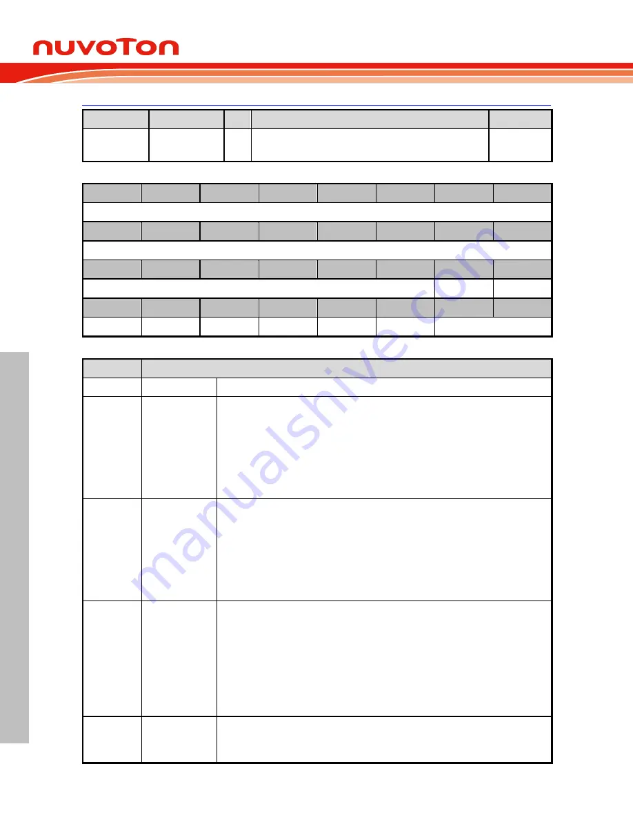
UART Line Control Register (UART_LINE)
Register
Offset
R/W
Description
Reset Value
UART_LINE
x=0,1
U0x0C R/W
UART Line Control Register
0x0000_0000
31
30
29
28
27
26
25
24
Reserved
23
22
21
20
19
18
17
16
Reserved
15
14
13
12
11
10
9
8
Reserved
RXDINV
TXDINV
7
6
5
4
3
2
1
0
PSS
BCB
SPE
EPE
PBE
NSB
WLS
Bits
Description
[31:10]
Reserved
Reserved.
[9]
RXDINV
RX Data Inverted
0 = Received data signal inverted Disabled.
1 = Received data signal inverted Enabled.
Note1:
Before setting this bit, TXRXDIS (UART_FUNCSEL[3]) should be set then waited
for TXRXACT (UART_FIFOSTS[31]) is cleared. When the configuration is done, cleared
TXRXDIS (UART_FUNCSEL[3]) to activate UART controller.
Note2:
This bit is valid when FUNCSEL (UART_FUNCSEL[2:0]) is select UART, LIN, or
RS485 function.
[8]
TXDINV
TX Data Inverted
0 = Transmitted data signal inverted Disabled.
1 = Transmitted data signal inverted Enabled.
Note1:
Before setting this bit, TXRXDIS (UART_FUNCSEL[3]) should be set then waited
for TXRXACT (UART_FIFOSTS[31]) is cleared. When the configuration is done, cleared
TXRXDIS (UART_FUNCSEL[3]) to activate UART controller.
Note2:
This bit is valid when FUNCSEL (UART_FUNCSEL[2:0]) is select UART, LIN, or
RS485 function.
[7]
PSS
Parity Bit Source Selection
The parity bit can be selected to be generated and checked automatically or by software.
0 = Parity bit is generated by EPE (UART_LINE[4]) and SPE (UART_LINE[5]) setting and
checked automatically.
1 = Parity bit generated and checked by software.
Note1:
This bit has effect only when PBE (UART_LINE[3]) is set.
Note2:
If PSS is 0, the parity bit is transmitted and checked automatically. If PSS is 1, the
transmitted parity bit value can be determined by writing PARITY (UART_DAT[8]) and the
parity bit can be read by reading PARITY (UART_DAT[8]).
[6]
BCB
Break Control Bit
0 = Break Control Disabled.
1 = Break Control Enabled.


