


M0A21/M0A23 Series
May 06, 2022
Page
358
of 746
Rev 1.02
M0
A21
/M
0
A
2
3
SE
RIES
TEC
H
NICAL
RE
FEREN
C
E
M
ANUAL
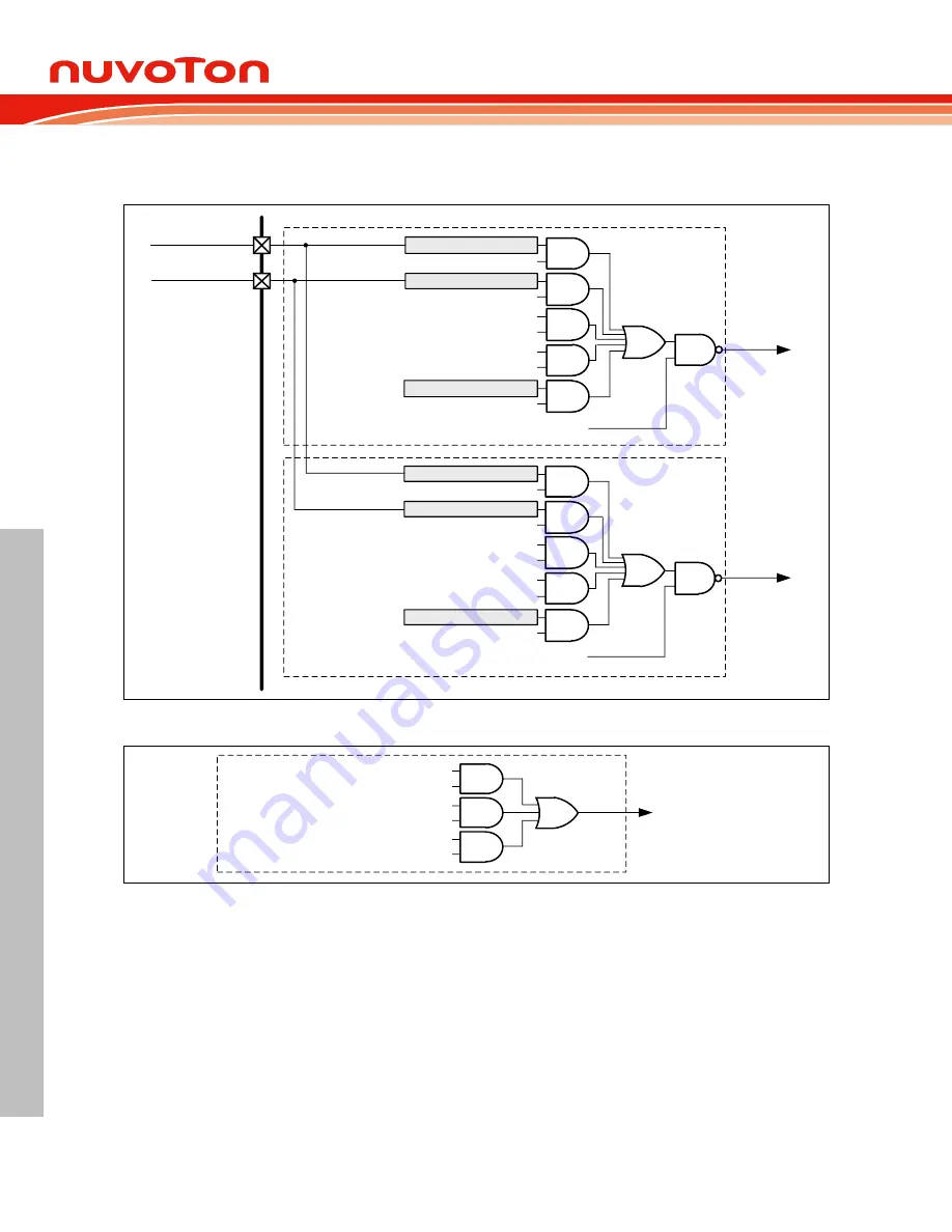
specified to several different system fail conditions. These conditions include clock fail, Brown-out
detect, and Core lockup. Figure 6.10-29 shows that by setting corresponding enable bits, the enabled
system fail condition can be one of the sources to issue the Brake system fail to the PWM brake.
BRKLTRG0 (PWM_SWBRK[8])
ACMP0_O
ACMP1_O
BRKP0EEN (PWM_BRKCTL0[4])
Brake Noise Filter
BRKP1EEN (PWM_BRKCTL0[5])
CPO0EBEN (PWM_BRKCTL0[0])
CPO1EBEN (PWM_BRKCTL0[1])
PWM_BRAKE0
Brake Noise Filter
PWM_BRAKE1
Brake
Function
Brake
Function
Edge Detect
Brake Source
Level Detect
Brake Source
Brake System Fail
SYSEBEN (PWM_BRKCTL0[7])
ACMP0_O
ACMP1_O
BRKP0LEN (PWM_BRKCTL0[12])
Brake Noise Filter
BRKP1LEN (PWM_BRKCTL0[13])
CPO0LBEN (PWM_BRKCTL0[8])
CPO1LBEN (PWM_BRKCTL0[9])
Brake Noise Filter
Brake System Fail
SYSLBEN (PWM_BRKCTL0[15])
BRKETRG0 (PWM_SWBRK[0])
Figure 6.10-28 Brake Source Block Diagram
CSSBRKEN (PWM_FAILBRK[0])
Clock Fail
BODBRKEN (PWM_FAILBRK[1])
Brown-Out Detect
CORBRKEN (PWM_FAILBRK[3])
Core Lockup
Brake Source
Brake System
Fail
Figure 6.10-29 Brake System Fail Block Diagram
6.10.5.20 Polarity Control
Each PWM port, from PWM_CH0 to PWM_CH5, has an independent polarity control module to
configure the polarity of the active state of the PWM output. By default, the PWM output is active high.
This implies the PWM OFF state is low and ON state is high. This definition is variable through setting
the PWM Negative Polarity Control Register (PWM_POLCTL), for each individual PWM channel. Figure
6.10-30 shows the initial state before PWM starting with different polarity settings.


