CHAPTER 9 8-BIT TIMER H
User’s Manual U16896EJ2V0UD
331
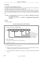
Setting
<1> Set each register.
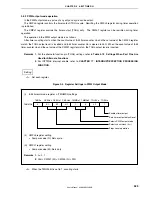
Figure 9-7. Register Settings in Carrier Generator Mode
•
8-bit timer H mode register n (TMHMDn)
0
0/1
0/1
0/1
0
Enables timer output
Sets timer output default level
Selects carrier generator mode
Selects count clock (f
CNT
)
Stops count operation
1
0/1
1
TMMDn0 TOLEVn
TOENn
CKSHn1
CKSHn2
TMHEn
TMHMDn
CKSHn0 TMMDn1
•
CMPn0 register:
Compare value
•
CMPn1 register:
Compare value
•
TMCYCn register:
RMCn = 1
... Remote control output enable bit
NRZBn = 0/1 ... Carrier output enable bit
•
TCL5n, TMC5n registers: Refer to
8.3 Registers
.
Remark
n = 0, 1
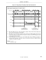
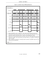
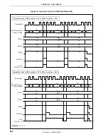
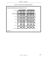
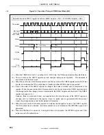
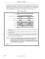
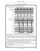
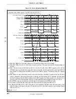
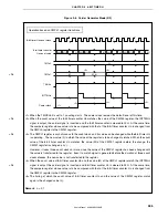
<2> When the TMHEn bit is set to 1, 8-bit timer Hn count operation starts.
<3> When the TMC5n.TCE5n bit is set to 1, 8-bit timer/event counter 5n count operation starts.
<4> After the count operation is enabled, the first compare register to be compared is the CMPn0 register.
When the count value of 8-bit timer counter Hn and the set value of the CMPn0 register match, the
INTTMHn signal is generated, 8-bit timer counter Hn is cleared, and at the same time, the register that is
compared with 8-bit timer counter Hn changes from the CMPn0 register to the CMPn1 register.
<5> When the count value of 8-bit timer counter Hn and the set value of the CMPn1 register match, the
INTTMHn signal is generated, 8-bit timer counter Hn is cleared, and at the same time, the register that is
compared with 8-bit timer counter Hn changes from the CMPn1 register to the CMPn0 register.
<6> The carrier clock is obtained through the repetition of steps <4> and <5> above.
<7> The INTTM5n signal is synchronized with 8-bit timer Hn and output as the INTTM5Hn signal. This signal
becomes the data transfer signal of the NRZBn bit and the value of the NRZBn bit is transferred to the
NRZn bit.
<8> Write the next value to the NRZBn bit in the interrupt servicing programming that has been started by the
INTTM5Hn interrupt or after timing has been checked by polling the interrupt request flag. Write data to
count the next time to the CR5n register.
<9> When the NRZn bit becomes high level, the carrier clock is output from the TOHn pin.
<10> Any carrier clock can be obtained through the repetition of the above steps. To stop the count operation,
clear the TMHEn bit to 0.
<R>
Содержание ?PD703302
Страница 2: ...User s Manual U16896EJ2V0UD 2 MEMO ...

