


CHAPTER 6 16-BIT TIMER/EVENT COUNTER P (TMP)
User’s Manual U16896EJ2V0UD
207
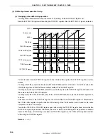
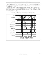
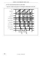
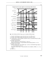
(b) Pulse width measurement with capture register
When pulse width measurement is performed with the TP0CCRa register used as a capture register,
software processing is necessary for reading the capture register each time the INTTP0CCa signal has
been detected and for calculating an interval.
FFFFH
16-bit counter
0000H
TP0CE bit
TIP00 pin input
TP0CCR0 register
INTTP0CC0 signal
TIP01 pin input
TP0CCR1 register
INTTP0CC1 signal
INTTP0OV signal
TP0OVF bit
0000H
D
00
D
01
D
02
D
03
D
04
D
10
D
00
D
11
D
01
D
12
D
04
D
13
D
02
D
03
D
10
0000H
D
11
D
12
D
13
Pulse interval
(D
00
)
Pulse interval
(
D
01
−
D
00
)
Pulse interval
(D
02
−
D
01
)
Pulse interval
(
D
03
−
D
02
)
Pulse interval
(
D
04
−
D
03
)
Pulse interval
(D
10
)
Pulse interval
(
D
11
−
D
10
)
Pulse interval
(
D
12
−
D
11
)
Pulse interval
(
D
13
−
D
12
)
Cleared to 0 by
CLR instruction
Cleared to 0 by
CLR instruction
Cleared to 0 by
CLR instruction
When executing pulse width measurement in the free-running timer mode, two pulse widths can be
measured with one channel.
To measure a pulse width, the pulse width can be calculated by reading the value of the TP0CCRa register
in synchronization with the INTTP0CCa signal, and calculating the difference between the read value and
the previously read value.
Remark
a = 0, 1
Содержание ?PD703302
Страница 2: ...User s Manual U16896EJ2V0UD 2 MEMO ...