CHAPTER 6 16-BIT TIMER/EVENT COUNTER P (TMP)
User’s Manual U16896EJ2V0UD
221
6.6 Eliminating Noise on Capture Trigger Input Pin (TIP0a)
The TIP0a pin has a digital noise eliminator.
However, this circuit is valid only when the pin is used as a capture trigger input pin; it is invalid when the pin is
used as an external event count input pin or external trigger input pin.
Digital noise can be eliminated by specifying the alternate function of the TIP0a pin using the PMC3, PFC3, and
PFCE3 registers.
The number of times of sampling can be selected from three or two by using the PaNFC.PaNFSTS bit. The
sampling clock can be selected from f
XX
, f
XX
/2, f
XX
/4, f
XX
/16, f
XX
/32, or f
XX
/64, by using the PaNFC.PaNFC2 to
PaNFC.PaNFC0 bits.
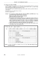
(1) TIP0a noise elimination control register (PaNFC)
This register is used to select the sampling clock and the number of times of sampling for eliminating digital
noise.
This register can be read or written in 8-bit or 1-bit units.
Reset sets this register to 00H.
0
PaNFC
(a = 0, 1)
PaNFSTS
0
0
0
PaNFC2
PaNFC1
PaNFC0
Number of times of sampling = 3
Number of times of sampling = 2
PaNFSTS
0
1
Setting of number of times of sampling for eliminating digital noise
After reset: 00H R/W Address: P0NFC FFFFFB00H, P1NFC FFFFFB04H
f
XX
f
XX
/2
f
XX
/4
f
XX
/16
f
XX
/32
f
XX
/64
PaNFC2
0
0
0
0
1
1
PaNFC1
0
0
1
1
0
0
PaNFC0
0
1
0
1
0
1
Sampling clock selection
Setting prohibited
Other than above
Cautions 1. Enable starting the 16-bit counter of TMP0 (TP0CTL.TP0CE bit = 1) after the lapse of the
sampling clock period
×
number of times of sampling.
2. Be sure to clear bits 7, 5 to 3 to “0”.
Содержание ?PD703302
Страница 2: ...User s Manual U16896EJ2V0UD 2 MEMO ...


