CHAPTER 6 16-BIT TIMER/EVENT COUNTER P (TMP)
User’s Manual U16896EJ2V0UD
174
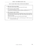
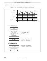
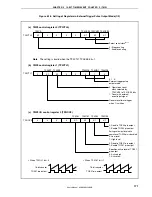
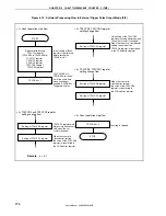
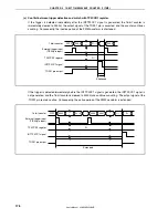
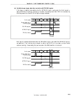
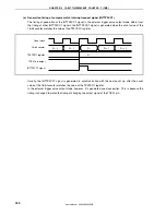
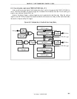
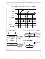
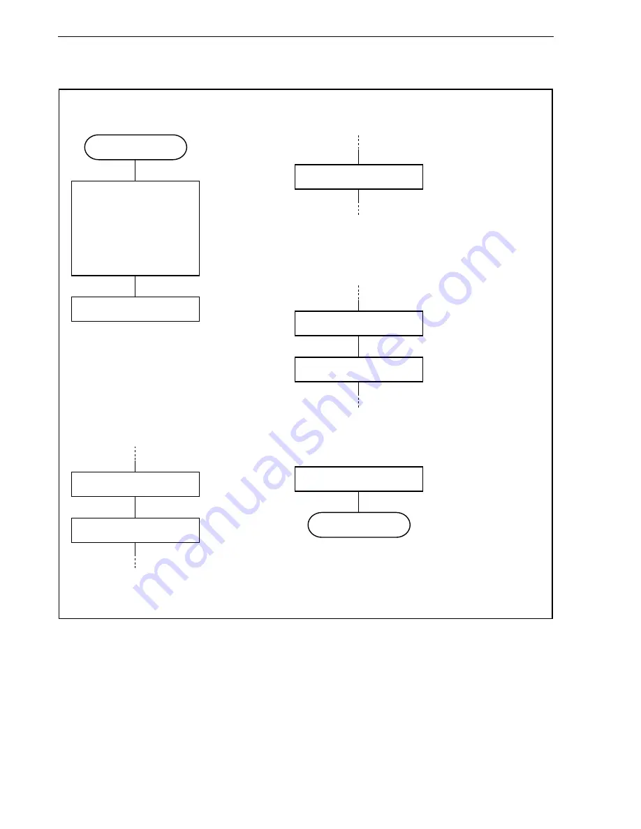
Figure 6-19. Software Processing Flow in External Trigger Pulse Output Mode (2/2)
TP0CE bit = 1
Setting of TP0CCR0 register
Register initial setting
TP0CTL0 register
(TP0CKS0 to TP0CKS2 bits)
TP0CTL1 register,
TP0IOC0 register,
TP0IOC2 register,
TP0CCR0 register,
TP0CCR1 register
Initial setting of these
registers is performed
before setting the
TP0CE bit to 1.
The TP0CKS0 to
TP0CKS2 bits can be
set at the same time
when counting is
enabled (TP0CE bit = 1).
Trigger wait status
TP0CCR1 register write
processing is necessary
only when the set
cycle is changed.
When the counter is
cleared after setting,
the value of the TP0CCRa
register is transferred to
the CCRa buffer register.
START
Setting of TP0CCR1 register
<1> Count operation start flow
<2> TP0CCR0 and TP0CCR1 register
setting change flow
Setting of TP0CCR0 register
When the counter is
cleared after setting,
the value of the TP0CCRa
register is transferred to
the CCRa buffer register.
Setting of TP0CCR1 register
<4> TP0CCR0, TP0CCR1 register
setting change flow
Only writing of the TP0CCR1
register must be performed when
the set duty factor is changed.
When the counter is cleared after
setting, the value of the
TP0CCRa register is transferred
to the CCRa buffer register.
Setting of TP0CCR1 register
<3> TP0CCR0, TP0CCR1 register
setting change flow
TP0CE bit = 0
Counting is stopped.
STOP
<5> Count operation stop flow
Remark
a = 0, 1
Содержание ?PD703302
Страница 2: ...User s Manual U16896EJ2V0UD 2 MEMO ...

