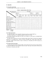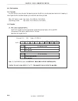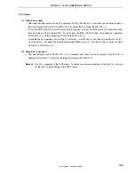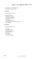
CHAPTER 6 16-BIT TIMER/EVENT COUNTER P (TMP)
User’s Manual U16896EJ2V0UD
138
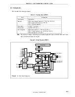
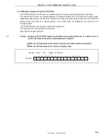
(1) 16-bit counter
This 16-bit counter can count internal clocks or external events.
The count value of this counter can be read by using the TP0CNT register.
When the TP0CTL0.TP0CE bit = 0, the value of the 16-bit counter is FFFFH. If the TP0CNT register is read at
this time, 0000H is read.
Reset sets the TP0CE bit to 0. Therefore, the 16-bit counter is set to FFFFH.
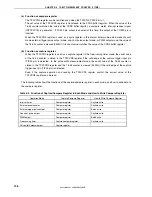
(2) CCR0 buffer register
This is a 16-bit compare register that compares the count value of the 16-bit counter.
When the TP0CCR0 register is used as a compare register, the value written to the TP0CCR0 register is
transferred to the CCR0 buffer register. When the count value of the 16-bit counter matches the value of the
CCR0 buffer register, a compare match interrupt request signal (INTTP0CC0) is generated.
The CCR0 buffer register cannot be read or written directly.
Reset sets the TP0CCR0 register to 0000H. Therefore, the CCR0 buffer register is set to 0000H.
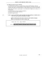
(3) CCR1 buffer register
This is a 16-bit compare register that compares the count value of the 16-bit counter.
When the TP0CCR1 register is used as a compare register, the value written to the TP0CCR1 register is
transferred to the CCR1 buffer register. When the count value of the 16-bit counter matches the value of the
CCR1 buffer register, a compare match interrupt request signal (INTTP0CC1) is generated.
The CCR1 buffer register cannot be read or written directly.
Reset sets the TP0CCR1 register to 0000H. Therefore, the CCR1 buffer register is set to 0000H.
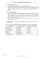
(4) Edge detector
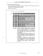
This circuit detects the valid edges input to the TIP00 and TIP01 pins. No edge, rising edge, falling edge, or
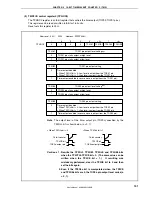
both the rising and falling edges can be selected as the valid edge by using the TP0IOC1 and TP0IOC2
registers.
(5) Output controller
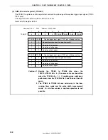
This circuit controls the output of the TOP00 and TOP01 pins. The output controller is controlled by the
TP0IOC0 register.
(6) Selector
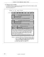
This selector selects the count clock for the 16-bit counter. Eight types of internal clocks or an external event
can be selected as the count clock.
(7) Digital noise eliminator
This circuit is valid only when the TIP00 and TIP01 pins are used as a capture trigger input pin.
This circuit is controlled by the P0NFC and P1NFC registers.
Содержание ?PD703302
Страница 2: ...User s Manual U16896EJ2V0UD 2 MEMO ...


