CHAPTER 8 8-BIT TIMER/EVENT COUNTER 5
User’s Manual U16896EJ2V0UD
297
8.3 Registers
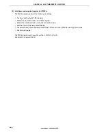
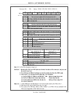
The following two registers are used to control 8-bit timer/event counter 5n.
•
Timer clock selection register 5n (TCL5n)
•
8-bit timer mode control register 5n (TMC5n)
Remark
To use the functions of the TI5n and TO5n pins, refer to
Table 4-12 Settings When Port Pins Are
Used for Alternate Functions
.
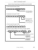
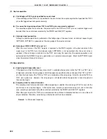
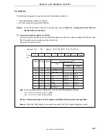
(1) Timer clock selection register 5n (TCL5n)
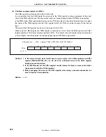
The TCL5n register sets the count clock of 8-bit timer/event counter 5n and the valid edge of the TI5n pin input.
The TCL5n register can be read or written in 8-bit units.
Reset sets this register to 00H.
Falling edge of TI5n
Rising edge of TI5n
f
XX
f
XX
/2
f
XX
/4
f
XX
/64
f
XX
/256
INTTM010
Count clock selection
Note
TCL5n2
0
0
0
0
1
1
1
1
TCL5n1
0
0
1
1
0
0
1
1
TCL5n0
0
1
0
1
0
1
0
1
20 MHz
10 MHz
–
–
Setting prohibited
100 ns
200 ns
3.2 s
12.8 s
–
–
–
100 ns
200 ns
0.4 s
6.4 s
25.6 s
–
Clock
f
XX
0
TCL5n
(n = 0, 1)
0
0
0
0
TCL5n2
TCL5n1
TCL5n0
After reset: 00H R/W Address: TCL50 FFFFF5C4H, TCL51 FFFFF5C5H
7
6
5
4
3
2
1
0
μ
μ
μ
μ
μ
Note
When the internal clock is selected, set so as to satisfy the following conditions.
V
DD
= 4.0 to 5.5 V: Count clock
≤
10 MHz
V
DD
= 2.7 to 4.0 V: Count clock
≤
5 MHz
Caution Before overwriting the TCL5n register with different data, stop the timer operation.
Remark
When the TM5n register is connected in cascade, the TCL51 register settings are invalid.
Содержание ?PD703302
Страница 2: ...User s Manual U16896EJ2V0UD 2 MEMO ...

