background image

Child restraint

Seat and seat belts

4-21

4

E00406602283

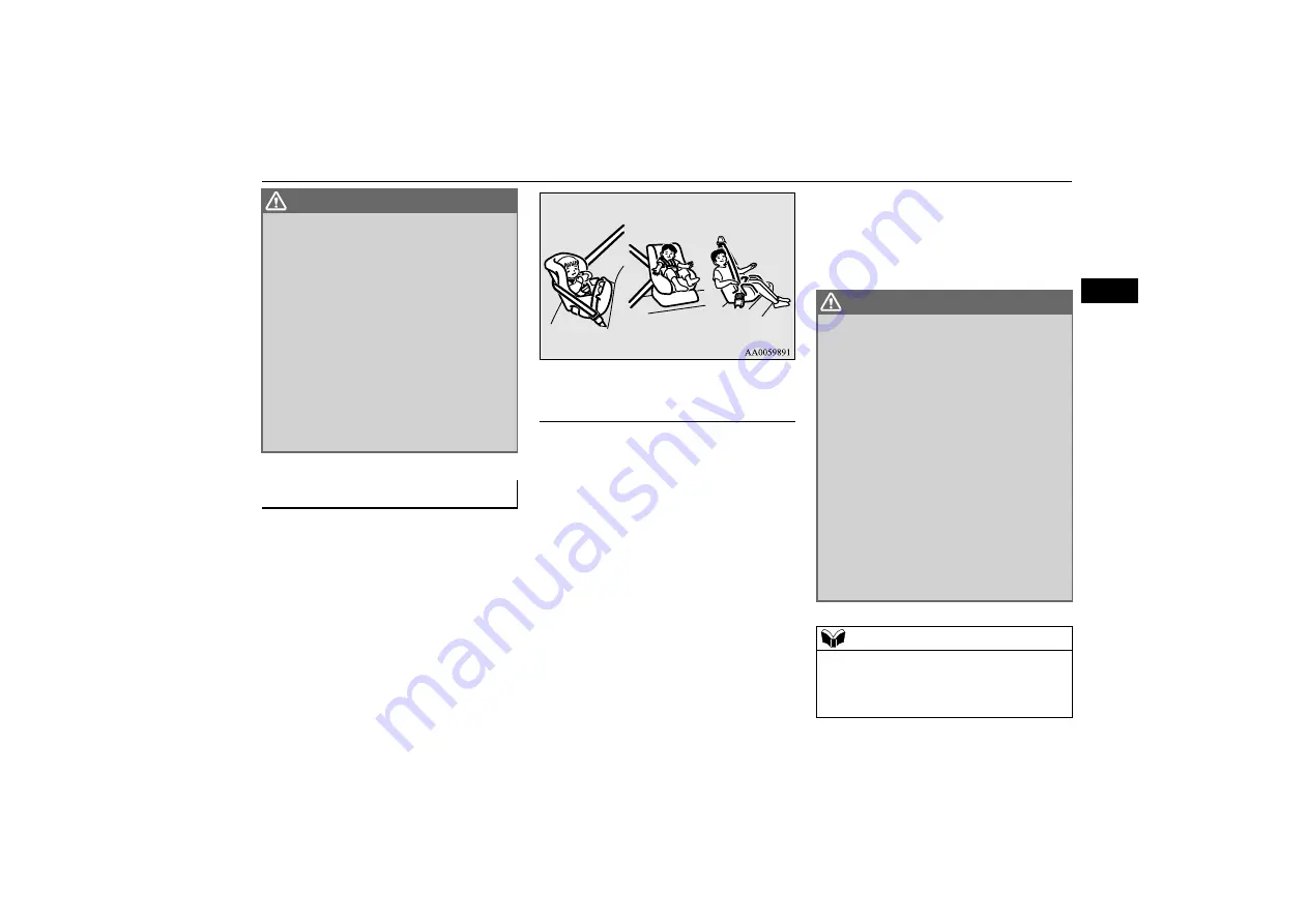
When transporting infants and small children
in your vehicle, follow the instruction given
below.

For small infants, an infant carrier should
be used. For small children whose height
when seated allows the shoulder belt to lie
in contact with the face or the throat, a
child seat should be used.

The child restraint system should be
appropriate for your child’s weight and
height and properly fit the vehicle. For a
higher degree of safety: THE CHILD
RESTRAINT SYSTEM SHOULD BE
INSTALLED IN THE REAR SEAT.

Before purchasing a child restraint sys-
tem, try installing it in the rear seat to
make sure there is a good fit. Because of
the location of the seat belt buckles and
the shape of the seat cushion, it may be
difficult to securely install some manufac-
turer’s child restraint systems.

If the child restraint system can be pulled
forward or to either side easily on the seat
cushion after the seat belt has been tight-
ened, choose another manufacturer’s child
restraint system.

WARNING

A REARWARD FACING CHILD
RESTRAINT must NOT be used in the
front passenger seat if the front passen-
ger’s airbag has not been deactivated. The
force of an inflating airbag could kill or
cause serious injuries to the child. A rear-
ward facing child restraint should be used
in the rear seat.

A FORWARD FACING CHILD
RESTRAINT should be used in the rear
seat whenever possible; if it must be used
in the front passenger seat, turn off the
front passenger’s airbag ON-OFF switch.
Failure to do so could kill or cause serious
injuries to the child.

Infants and small children 

Instruction: 

WARNING

When installing a child restraint system,
refer to the instructions provided by the
manufacturer of the restraint system.
Failure to do so can result in severe or
fatal injury to your child.

After installation, push and pull the child
restraint system back and forth, and side
to side, to see that it is positively secured.
If the child restraint system is not installed
securely, it may cause injury to the child
or other occupants in the case of accident
or sudden stops.

When the child restraint system is not in
use, keep your child restraint system
secured with the seat belt or remove it
from the vehicle in order to prevent it
from being thrown around inside the vehi-
cle during an accident.

NOTE

Depending on the seating position in the
vehicle and the child restraint system that
you have, the child restraint can be attached
using one of the following two ways:

Содержание PAJERO SPORT

Страница 1: ...locally produced part the operat ing procedure specifications maintenance intervals and other contents found in this owner s manual may not sometimes apply to it Please leave this owner s manual in this vehicle at time of resale The next owner will appreciate having access to the information contained in this owner s manual Foreword Throughout this owner s manual the words WARNING and CAUTION appe...

Страница 2: ... 4 5 6 7 8 9 10 11 Overview Quick guide General information Locking and unlocking Seat and seat belts Instruments and controls Starting and driving For pleasant driving For emergencies Vehicle care Maintenance Specifications ...

Страница 3: ...outside rear view mirrors P 6 12 Lock switch P 3 33 Electric window control switch P 3 32 Bonnet release lever P 10 3 Fuel tank filler door release lever P 2 2 Active stability control ASC OFF switch P 6 61 Instruments Type A P 5 2 Instruments Type B P 5 17 Wiper and washer switch P 5 84 Rear wiper and washer switch P 5 86 Shift paddles P 6 23 Sonar switch P 6 103 6 107 Forward Collision Mitigatio...

Страница 4: ...tors P 7 3 Supplemental restraint system SRS airbag for front passenger s seat P 4 28 4 32 Air conditioning P 7 2 Centre ventilators P 7 3 Rear window demister switch P 5 88 Steering wheel height and reach adjustment lever P 6 10 Multi information display switch P 5 4 Adaptive Cruise control System ACC P 6 69 Off Road mode selector P 6 34 Electric parking brake switch P 6 4 Hill Descent Control sw...

Страница 5: ...P 4 28 4 33 Supplemental restraint system SRS side airbag for front seat P 4 28 4 35 Second seats P 4 5 Child restraint system with ISOFIX mountings P 4 26 Lower anchorage location P 4 26 Third seats P 4 6 Armrest P 4 5 Cup holder P 7 24 Luggage compartment lamp P 7 19 7 21 10 22 Accessory socket P 7 16 Cup holder P 7 25 Supplemental restraint system SRS curtain airbag P 4 28 4 35 Rear personal la...

Страница 6: ...Luggage area Overview Quick guide 1 4 1 E08500301611 Luggage area Luggage hooks P 7 26 Luggage floor boxes P 7 22 7 23 Jack P 8 6 Tools P 8 6 Tyre repair kit P 8 7 ...

Страница 7: ...5 81 10 21 Outside rear view mirrors P 6 12 Side view camera P 6 113 Headlamp washer P 5 87 Active Cornering Lights ACL P 5 82 10 21 Headlamps high low beam P 5 79 10 21 Front turn signal lamps P 5 81 10 21 10 22 Position lamps P 5 79 10 21 Daytime running lamps P 5 80 10 21 Front fog lamps P 5 83 10 21 Front view camera P 6 113 Ultrasonic misacceleration Mitigation System sensor P 6 94 Sensor sys...

Страница 8: ...ng tyres P 8 14 Tyre rotation P 10 12 Snow tyres P 10 13 Tyre chains P 10 13 High mounted stop lamp P 10 21 Rear wiper and washer P 5 86 Rear view camera P 6 110 6 113 Multi Around Monitor P 6 113 Blind Spot Warning Sensor P 6 95 Ultrasonic misacceleration Mitigation System sensor P 6 94 Reversing sensor system sensor P 6 102 Sensor system sensor P 6 105 Blind Spot Warning lamp P 6 95 Glass antenn...

Страница 9: ... unlocking the tailgate Refer to Operating the electric tailgate using the keyless operation key on page 3 20 When you are carrying the keyless operation key and within the operating range if you press the driver s or front passenger s door switch A the tailgate LOCK switch B when locking or pull the tailgate handle lever C tailgate open switch D when unlocking the doors and the tailgate are locke...

Страница 10: ... lever towards you Refer to Wiper and washer switch on page 5 84 Tailgate switches Vehicles with electric tailgate Around the driver s seat 1 Wiper and washer switch MIST Misting function The wipers will operate once OFF Off AUTO Auto wiper control Rain sensor The wipers will automatically operate depending on the degree of wetness on the windscreen LO Slow HI Fast ...

Страница 11: ... turn signal lamps flash when the lever is operated Refer to Turn signal lever on page 5 81 2 Steering wheel height and reach adjustment A Locked B Release 3 Combination headlamps OFF All lamps off AUTO With the operation mode is in ON head lamps position tail licence plate and instrument panel lamps turn on and off automatically in accordance with outside light level All lamps turn off automati c...

Страница 12: ...2 Open the fuel tank filler door The fuel tank filler is located on the rear left side of your vehicle Refer to Filling the fuel tank on page 2 2 4 Engine switch OFF The indicator lamp A on the engine switch turns off ACC The indicator lamp on the engine switch illuminates orange ON The indicator lamp on the engine switch illuminates green 5 Electric remote controlled out side rear view mirrors L ...

Страница 13: ...ed This position is for normal driving 7 Electric window control 1 Driver s door window 2 Front passenger s door window 3 Rear left door window 4 Rear right door window 5 Lock switch Lock switch 8 Speed automatic transmission with sports mode Selector lever operation The lock button must be pushed while the brake pedal is depressed to move the selector lever The lock button must be pushed to move ...

Страница 14: ... Rear differential lock P 6 36 Active Active Active The Off Road mode and the rear differential lock cannot be used at the same time When the rear differential lock is set to ON the Off Road mode turns off In addition when the rear differential lock is ON the Off Road mode will be deactivated even if the Off Road mode selector is operated CAUTION When driving on the off road confirm the conditions...

Страница 15: ...d mode indicator display P 6 35 2 Drive mode indicator display P 6 27 3 mark display P 5 6 4 Forward Collision Mitigation System FCM and Ultrasonic misacceleration Mitigation System UMS OFF indica tor display P 6 83 6 90 5 Cruise control indicator display P 6 63 6 Adaptive Cruise Control System ACC display P 6 69 7 or mark indicator P 5 6 8 Information screen P 5 5 9 Selector lever position displa...

Страница 16: ...tion Mitigation System UMS OFF indicator display P 6 83 6 90 4 Analog gauge speedometer 5 Digital speedometer 6 Sub unit speedometer P 5 39 7 mark display P 5 43 8 Hill Descent Control indicator lamp P 6 55 9 Rear differential lock indicator lamp P 6 36 10 Drive mode indicator display P 6 27 11 Off Road mode indicator display P 6 35 12 Brake auto hold standby indicator lamp white P 6 51 Brake auto...

Страница 17: ...ACC display P 6 69 Blind Spot Warning display P 6 95 16 Selector lever position display P 6 22 17 Odometer P 5 44 18 Outside temperature display P 5 43 19 Analog gauge tachometer The tachometer indicates the engine speed r min The tachometer can help you obtain more economical driving and also warns you of excessive engine speeds Red zone ...

Страница 18: ... Hill Descent Control indicator lamp P 6 55 8 Rear differential lock indicator lamp P 6 36 9 Drive mode indicator display P 6 27 10 Off Road mode indicator display P 6 35 11 Sub unit speedometer P 5 39 12 Brake auto hold standby indicator lamp white P 6 51 Brake auto hold indicator lamp green P 6 52 13 Blind Spot Warning BSW indicator lamp P 6 98 14 Multi information screen P 5 35 Interrupt displa...

Страница 19: ...er The tachometer indicates the engine speed r min The tachometer can help you obtain more economical driving and also warns you of excessive engine speeds Red zone 5 Digital speedometer 6 Sub unit speedometer P 5 39 7 mark display P 5 43 8 Hill Descent Control indicator lamp P 6 55 9 Rear differential lock indicator lamp P 6 36 10 Drive mode indicator display P 6 27 11 Off Road mode indicator dis...

Страница 20: ...lay Cruise control indicator display P 6 63 Adaptive Cruise Control System ACC display P 6 69 Blind Spot Warning display P 6 95 16 Selector lever position display P 6 22 17 Odometer P 5 44 18 Outside temperature display P 5 43 19 Instant fuel consumption indicator ...

Страница 21: ...s the engine speed r min The tachometer can help you obtain more economical driving and also warns you of excessive engine speeds Red zone 5 Digital speedometer 6 mark display P 5 43 7 Hill Descent Control indicator lamp P 6 55 8 Rear differential lock indicator lamp P 6 36 9 Drive mode indicator display P 6 27 10 Off Road mode indicator display P 6 35 11 Sub unit speedometer P 5 39 12 Brake auto ...

Страница 22: ...ick guide 1 20 1 16 Driving support display Cruise control indicator display P 6 63 Adaptive Cruise Control System ACC display P 6 69 Blind Spot Warning display P 6 95 17 Odometer P 5 44 18 Outside temperature display P 5 43 ...

Страница 23: ...een P 5 34 Interrupt display screen P 5 42 5 Digital speedometer 6 Sub unit speedometer P 5 39 7 mark display P 5 43 8 Hill Descent Control indicator lamp P 6 55 9 Rear differential lock indicator lamp P 6 36 10 Drive mode indicator display P 6 27 11 Off Road mode indicator display P 6 35 12 Analog gauge tachometer The tachometer indicates the engine speed r min The tachometer can help you obtain ...

Страница 24: ... display Cruise control indicator display P 6 63 Adaptive Cruise Control System ACC display P 6 69 Blind Spot Warning display P 6 95 16 Selector lever position display P 6 22 17 Odometer P 5 44 18 Outside temperature display P 5 43 19 Analog gauge speedometer ...

Страница 25: ...39 6 mark display P 5 43 7 Hill Descent Control indicator lamp P 6 55 8 Rear differential lock indicator lamp P 6 36 9 Drive mode indicator display P 6 27 10 Off Road mode indicator display P 6 35 11 Analog gauge tachometer The tachometer indicates the engine speed r min The tachometer can help you obtain more economical driving and also warns you of excessive engine speeds Red zone 12 Brake auto ...

Страница 26: ...ur LCD meter on page 5 19 16 Driving support display Cruise control indicator display P 6 63 Adaptive Cruise Control System ACC display P 6 69 Blind Spot Warning display P 6 95 17 Odometer P 5 44 18 Outside temperature display P 5 43 19 Analog gauge speedometer ...

Страница 27: ......

Страница 28: ...ling the fuel tank 2 2 Installation of accessories 2 4 Modification alterations to the electrical or fuel systems 2 4 Genuine parts 2 5 Safety and disposal information for used engine oil 2 5 Event Data Recording 2 5 MITSUBISHI Remote Control 2 6 ...

Страница 29: ...tailed please contact the nearest author ised MITSUBISHI MOTORS dealer Filling the fuel tank WARNING When handling fuel comply with the safety regulations displayed by garages and filling stations Fuel is highly flammable and explosive You could be burned or seriously injured when handling it When refueling your vehicle always turn the engine off and keep away from flames sparks and smok ing mater...

Страница 30: ...ly do not fill with fuel any more 6 To close turn the fuel cap slowly clock wise until you hear clicking sounds then gently push the fuel tank filler door closed Refueling 1 Remove 2 Close CAUTION Since the fuel system may be under pressure remove the fuel cap slowly This relieves any pressure or vacuum that might have built up in the fuel tank If you hear a hissing sound wait until it stops befor...

Страница 31: ... officially author ised for example by a general operators per mit an appraisal for the part or through the execution of the part in an officially approved manner of construction or when a single operation permit following the attachment or installation of such parts it cannot be deduced from that alone that the driving safety of your vehicles has not been affected Consider also that there basical...

Страница 32: ...00205900195 This vehicle is equipped with an event data recorder EDR The main purpose of an EDR is to record in certain crash or near crash like situations such as an airbag deployment or hitting a road obstacle data that will assist in under standing how a vehicle s systems performed The EDR is designed to record data related to vehicle dynamics and safety systems for a short period of time typic...

Страница 33: ...rations when leaving the vehicle it is notified to the Bluetooth device Operation assist If the buzzer sounds or the vehicle does not react while you operate some from the outside of vehicle the Bluetooth device notifies solutions NOTE EDR data are recorded by your vehicle only if a non trivial crash situation occurs no data are recorded by the EDR under normal driv ing conditions and no personal ...

Страница 34: ... This product conforms to the Radio Law Use it only in your country People with implantable cardiac pacemak ers or implantable cardiovascular defi brillators should keep away from the devices The operation of electro medical appara tus may be affected When you do not use the MITSUBISHI Remote Control set the keyless operation system to be disabled Refer to Keyless operation system on page 3 6 Neve...

Страница 35: ...ice away from these appliances and equipment If a Bluetooth device and a wireless LAN device are used simultaneously the com munication speed and range of each device may decrease Use your Bluetooth device away from wireless LAN devices Bluetooth devices may not communicate with the vehicle or may not operate nor mally or stably in the following environment or situations Check that the device can ...

Страница 36: ...screen to the function setting display Refer to 8 inch colour LCD meter switches on page 5 19 Refer to Function setting display on page 5 38 2 Operate the 8 inch colour LCD meter switches to select REMOTE Then press the Enter switch 3 Select the Device Initialization and press and hold the Enter switch for 2 sec onds or more 4 When the initialization is completed Success is displayed in the Status...

Страница 37: ...meter switches to select REMOTE Then press the Enter switch 3 Operate the 8 inch colour LCD meter switches to select the Select and press the Enter switch 4 Operate the 8 inch colour LCD meter switches to select the Device 1 or Device 2 and press the Enter switch to confirm the setting ...

Страница 38: ...3 2 Electronic immobilizer Anti theft starting system 3 3 Keyless entry system 3 3 Keyless operation system 3 6 Doors 3 14 Central door locks 3 15 Child protection rear doors 3 16 Tailgate 3 17 Security alarm system 3 29 Electric window control 3 32 ...

Страница 39: ...o water Keep away from magnetic key rings Keep away from audio systems personal computers TVs and any other equipment that generates a magnetic field Keep away from devices that emit strong electromagnetic waves such as cellular phones wireless devices and high fre quency equipment including medical devices Do not wash with ultrasonic cleaners or similar equipment Do not leave the key where it may...

Страница 40: ...nic immobilizer Anti theft starting system NOTE If the engine does not start contact an authorised MITSUBISHI MOTORS dealer If you lose one of them contact an author ised MITSUBISHI MOTORS dealer as soon as possible To obtain a replacement or extra spare key take your vehicle and all remain ing keys to an authorised MITSUBISHI MOTORS dealer All the keys have to be re registered in the immobiliser ...

Страница 41: ...only during unlocking The confirmation function this indicates locking or unlocking of the doors and the tailgate with the blink of the turn signal lamps can be deactivated The number of times the turn signal lamps are blinked by the confirmation function can be changed The buzzer sound can be activated when a keyless operation is done The keyless entry system does not operate in the following con...

Страница 42: ...r view mirrors will extend again NOTE Procedure for replacing the key battery WARNING Do not swallow a coin type battery This product contains coin type battery If a coin type battery is swallowed it can cause severe internal burns and can lead to death There have been cases where a swallowed battery has caused severe internal burns in just 2 hours Keep new and used batteries away from children If...

Страница 43: ... 3 The driver should always carry the keyless operation key This key is necessary for lock ing and unlocking the doors and the tailgate starting the engine and otherwise operating the vehicle so before locking and leaving the vehicle be sure to check that you have the keyless operation key NOTE Be sure to perform the procedure with the MITSUBISHI mark facing you If the MITSUBISHI mark is not facin...

Страница 44: ... may be unstable When there is equipment nearby that emits strong radio waves such as a power sta tion a radio TV broadcasting station or an airport The keyless operation system is carried together with a communications device such as a cellular phone or radio set or with an electronic device such as a personal computer The keyless operation key is touching or covered by a metal object A keyless e...

Страница 45: ...ar to the ground or high up the system may not oper ate If the keyless operation key is within the operating range even someone not carrying the key can lock and unlock the doors and tailgate by using the keyless operation func tion Operating range for starting the engine and changing the opera tion mode Forward direction Operating range NOTE NOTE Even if it is within the operating range if the ke...

Страница 46: ...l door locks Tailgate on pages 3 14 3 15 and 3 17 Locking the doors and tailgate Tailgate switches except for vehicles equipped with the electric tailgate Tailgate switches vehicles equipped with the electric tailgate Unlocking the doors and tailgate NOTE The outside rear view mirrors automatically retract extend when all the doors and the tail gate are locked unlocked using the keyless operation ...

Страница 47: ...onds the turn signal lamps blink twice and the outer buzzer sounds twice NOTE Functions can be modified as stated below For further information please contact an authorised MITSUBISHI MOTORS dealer Activating the operation confirmation func tion blinking of the turn signal lamps only during locking or only during unlocking Disabling the operation confirmation func tion blinking of the turn signal ...

Страница 48: ...attery is completely dead Key not detected Inner buzzer sounds once When the engine switch is turned to the ACC or ON from OFF or when the engine is started the warning is activated if any of the following conditions is occurred Carrying another keyless operation key with a different code or the keyless operation key could be outside the operating range The battery of the keyless operation key is ...

Страница 49: ...vironment or electromagnetic conditions the warning may be activated Key lock in prevention system Inner buzzer sounds once Outer buzzer sounds approxi mately 3 seconds intermittently When the operation mode is in OFF if you close all the doors and the tailgate with the key less operation key left in the vehicle and you try to lock the doors and tailgate by pressing the driver s or front passenger...

Страница 50: ...ds approxi mately 3 seconds intermittently When the operation mode is in any mode other than OFF if you try to lock the doors and tail gate by pressing the driver s or front passenger s door lock unlock switch or the tailgate LOCK switch a warning is issued and you cannot lock the doors and tailgate Item Display Buzzer Note Solution ...

Страница 51: ...he driver s door when it is open To lock or unlock with the key 1 Lock 2 Unlock NOTE When locking or unlocking with the key all doors and the tailgate will be locked or unlocked Refer to Central door locks on page 3 15 As the vehicle is equipped with the keyless operation system the driver s door can be locked or unlocked with the emergency key Refer to Emergency key on page 3 10 To lock or unlock...

Страница 52: ... is prepared for rescue activities when an unexpected accident occurs Central door locks NOTE Repeated continuous operation between lock and unlock could activate the central door locking systems built in protection circuit and prevent the system from operating If this occurs wait approximately 1 minute before operating the central door lock sys tem When the driver s door is open the central door ...

Страница 53: ...y while driving Even when the operation mode is in ON the SRS warning lamp does not come on or it remains on The SRS warning lamp and or the warn ing display comes on while driving The central door lock system is broken down NOTE Even if the vehicle suffers significant defor mation from a collision etc depending on the location and angle of the collision as well as on the shape and condition of th...

Страница 54: ...here is a build up of snow or ice it should be removed before opening the tail gate If you open the tailgate without removing it there is a possibility that the tailgate may close suddenly due to the weight of that snow or ice When you open the tailgate make sure that the tailgate is opened fully and remains fully open If you only open the tailgate halfway there is a risk that the tailgate may dro...

Страница 55: ...gate and pry gently to open the lid 2 Move the lever B to open the tailgate 3 Push out on the tailgate to open it Operating the tailgate Except for the electric tailgate To open from outside the vehicle CAUTION When operating the tailgate handle lever A put your fingers to the position shown in the illustration and be careful not to pinch your fingers in the lever Front of the vehicle NOTE The tai...

Страница 56: ...the vehicle Refer to MITSUBISHI Remote Control on page 2 6 WARNING Always keep the release lever lid on tail gate closed when driving so that your lug gage cannot accidentally bump the lever and open the tailgate To close CAUTION When closing the tailgate do not close it directly putting the hands on the tailgate grip If the hands or arms got caught a seri ous injury could result Operating the tai...

Страница 57: ... it is operated with a load in a direction opposite to the operating direction the protection circuit is activated to switch automatic operation to manual operation If the electric tailgate operation switch is pressed or the hands free access is used while the electric tailgate is operating the electric tailgate stops moving If the switch is pressed or the hands free access is used again the elect...

Страница 58: ...switch is pressed once while the electric tailgate is operating the electric tailgate stops moving after the warning buzzer sounds If the inside electric switch is pressed for more than approximately 1 second again the electric tailgate moves in the opposite direc tion to the direction in which it was moving before E00315100032 The electric tailgate can be operated automat ically by pressing the t...

Страница 59: ...unds the hazard warning lamps flash and the electric tailgate opens E00315300034 The electric tailgate can be operated automat ically by making the kick motion sensor A on the lower right and left of the rear bumper sense the foot motion NOTE When the operation mode is ON the electric tailgate cannot be opened by pressing the inside electric tailgate switch unless the selector lever is in the P PA...

Страница 60: ... a slope unpaved road icy road surface etc be care ful not to injure yourself by falling Turn the automatic operation OFF before you wash or wax the surrounding area of the kick motion sensor or install remove a car cover etc If the hands free access remains on you may be injured due to a sudden oper ating of the electric tailgate resulting from a possible reaction of the kick motion sensor Refer ...

Страница 61: ...NOTE Make sure all doors and the tailgate are locked when leaving the vehicle If you operate the electric tailgate while the close and lock function is operating the elec tric tailgate stops moving and all doors and the tailgate are unlocked Refer to Automatic operation on page 3 19 Refer to Manual operation on page 3 27 If you perform unlocking operation while the close and lock function is opera...

Страница 62: ...d if the elec tric tailgate should trap a person or an object during automatic operation or if the sensors A on either side of the electric tailgate are hit by a person or luggage The warning buzzer sounds once for safety and the electric tailgate automatically moves in the direction opposite to the one in which it is operating Height memory NOTE The stop position of the electric tailgate can not ...

Страница 63: ...proximately 2 seconds or more to switch from ON to OFF or OFF to ON The setting is changed to the selected con dition For vehicles equipped with Instruments Type B 1 Operate the 8 inch colour LCD meter switches to switch the multi information screen to the function setting display If the safety mechanism is repeatedly acti vated the tailgate could be switched to man ual operation Be careful at thi...

Страница 64: ...of a straight blade or minus screwdriver into the notch of the lid A inside of the tailgate and pry gently to open the lid 2 Move the lever B to open the tailgate 3 Push out on the electric tailgate to open it WARNING If automatic operation is turned off while the electric tailgate is operating it will stop moving and switch to manual opera tion At this time the electric tailgate could open or clo...

Страница 65: ...the electric tailgate is closed manually Therefore be especially careful not to trap a hand or finger at this time Tailgate easy closer WARNING Be careful not to trap your hands or fin gers during operation of the tailgate easy closer If you think this could occur press an electric tailgate operation switch or use the hands free access The electric tailgate will return to the door ajar position CA...

Страница 66: ...tor lamp continues to blink with the indicator s reduced lit up duration time Once the system preparation mode has ended the system armed mode starts If an unlawful opening of any of the doors or tailgate is detected during the system armed mode the alarm will be activated to warn people around the vehicle of an abnormal condition Also if unlawful moving of the vehicle is attempted or a vehicle in...

Страница 67: ...yless operation func tion or the close and lock function the system preparation mode is activated The buzzer makes an intermittent beeping sound and the security indicator lamp in the instrument cluster flashes for confir mation NOTE The alarm will resume if unlawful actions are taken again even if the alarm has stopped System cancellation NOTE When lending the vehicle to another person or allowin...

Страница 68: ...ITSUBISHI MOTORS dealer NOTE The security alarm system can be activated when people are riding inside the vehicle or when the windows are open To prevent acci dental activation of the alarm do not set the system to the system armed mode while peo ple are riding in the vehicle Avoid leaving valuable items inside the vehi cle even when the security alarm system has been set to the active mode Cancel...

Страница 69: ...losed after which the system preparation mode will once again go into effect Putting the operation mode in ON Holding the keyless operation key and locking or unlocking the doors and the tailgate using the keyless operation func tion E00302201717 The electric windows can only be operated with the operation mode in ON E00302303611 Each door window opens or closes while the corresponding switch is o...

Страница 70: ...close any door windows other than the driver s door window To unlock push it once again 1 Driver s door window 2 Front passenger s door window 3 Rear left door window 4 Rear right door window 5 Lock switch WARNING Before operating the electric window con trol make sure that nothing is capable of being trapped head hand finger etc Never leave the vehicle without removing the key Never leave a child...

Страница 71: ... The safety mechanism is cancelled just before the window is fully closed This allows the window to close completely Therefore be especially careful that no fin gers are trapped in the window The safety mechanism is deactivated while the switch is pulled up Therefore be espe cially careful that fingers are not trapped in the door window opening NOTE The safety mechanism can be activated if the dri...

Страница 72: ...s 4 5 Third seats 4 6 Head restraints 4 7 Making a luggage area 4 9 Making a flat seat 4 13 Seat belts 4 14 Pregnant women restraint 4 19 Seat belt pre tensioner system and force limiter system 4 19 Child restraint 4 20 Seat belt inspection 4 28 Supplemental restraint system SRS airbag 4 28 ...

Страница 73: ...Seat arrangement 4 2 Seat and seat belts 4 E00400202043 By operating the front second or third seat select the desired seat arrangement Seat arrangement ...

Страница 74: ...Seat arrangement Seat and seat belts 4 3 4 Normal usage Flat seat P 4 13 Making a luggage area Folding the second seats P 4 9 Folding the third seatbacks forward P 4 11 Folding the third seats P 4 12 ...

Страница 75: ...eatbacks should always be in the almost upright position while the vehicle is in motion The protection provided by the seat belts may be reduced significantly when the seatback is reclined There is greater risk that the passenger will slide under the seat belt resulting in serious injury when the seatback is reclined Do not place objects under the seats This could prevent the seat from locking sec...

Страница 76: ...and adjust the seatback angle to the desired position 3 To adjust seat height Operate the switch as indicated by the arrows and adjust the seat height to the desired position If the entire switch is operated then the entire seat moves 4 To adjust seat cushion angle Operate the switch as indicated by the arrows and adjust the seat cushion angle to the desired position NOTE To prevent the battery fr...

Страница 77: ...sing the armrest the cup holder may come out automatically However this phenomenon does not indicate a malfunction A lock mechanism is released because of a shock by folding or returning the seat extremely hard When returning the armrest to the original position make sure to stow the cup holder To get in and out of the third seat Third seats WARNING For reasons of safety whenever passen gers sit i...

Страница 78: ...n accident pull up the head restraint to the locked posi tion To raise the head restraint move it upward To lower the restraint move it downward while pushing the height adjusting knob A in the direction of the arrow After adjust ment push the head restraint downward and make sure that it is locked Head restraints WARNING Driving without the head restraints in place can cause you and your passenge...

Страница 79: ...be installed in the hole with the adjusting knob A Third seats WARNING When a person sits in the second or the third seats pull up the head restraint to a height at which it locks in position Be sure to make this adjustment before start ing to drive Serious injuries could other wise be suffered in the result of an impact To remove Second seats Third seats To install CAUTION Confirm that the height...

Страница 80: ...he head restraint dif fers according to the seat Always use the correct head restraint provided for the seat and do not install the head restraint in the wrong direction Making a luggage area WARNING When driving the vehicle do not allow anyone to sit on the third seat if the second seat is folded The second seat could tip rearward in the event of hard braking a collision or sudden starts resultin...

Страница 81: ...taining band in the original position then gently lower the seat WARNING Be sure to securely retain the folded seat using the retaining bands Unless retained the seat may tip causing a serious acci dent CAUTION Do not allow any person to sit on the folded seat and do not place luggage on it The seat s mounting fittings could bend under the weight making it impossible for the seat to be retained on...

Страница 82: ...t to the lowest position Refer to Head restraints on page 4 7 2 Store the seat belt buckles in the storage pockets of the third seats Refer to Second and third seat belt stor age on page 4 18 3 Pull the lock release band A then lift the seat cushion forward 4 Pull the seatback lock release band B then tilt the seatback forward until you hear a click 1 Pull the seatback lock release band B then rai...

Страница 83: ...the head restraints of the third seat to the lowest position Refer to Head restraints on page 4 7 3 Store the seat belt buckles in the storage pockets on the third seats Refer to Second and third seat belt stor age on page 4 18 4 Pull the lock release band A then lift the seat cushion forward 5 Raise the stand C and then gently lower the seat cushion 6 Pull the seatback lock release band B then ti...

Страница 84: ...eat cushion 4 Push the seat cushion until you hear a click and the seat locks securely E00404302130 By removing the head restraints and fully reclining the seatbacks of the seats one large flat seat is achieved To return Making a flat seat WARNING Never drive with passengers on the flat seat This is highly dangerous CAUTION To make a flat seat stop the vehicle in a safe place Make sure the seat is...

Страница 85: ... the event of an accident it is the most important that the seat belts be worn correctly while you drive The front seat belts have a pre tensioner sys tem These belts are used the same way as a conventional seat belt Refer to Seat belt pre tensioner system and force limiter system on page 4 19 To ensure the seats are locked securely attempt to move them back and forth Do not jump on or impact the ...

Страница 86: ... reclined there is greater risk that the passenger will slide under the belt especially in a forward impact accident and may be injured by the belt or by striking the instrument panel or seatbacks Remove any twists when using the belt No modifications or additions should be made by the user which will either prevent the seat belt adjusting devices from oper ating to remove slack or prevent the sea...

Страница 87: ...r into position NOTE As the belt retracts automatically keep the latch plate held while retracting so that the belt stows slowly Failure to do this could damage the vehicle If the seat belt A or ring B becomes dirty the belt may not retract smoothly If the seat belt and ring are dirty clean them with a mild soap or detergent solution Seat belt reminder WARNING Do not install any accessory or stick...

Страница 88: ...into the buckle C 4 Insert the latch plate B into the buckle D WARNING When adjusting the seat belt anchor set it at a position that is sufficiently high so that the belt will make full contact with your shoulder but will not touch your neck Second centre 3 point type seat belt WARNING Be sure to securely connect the both latch plate A and B Failing to do so could sig nificantly reduce the amount ...

Страница 89: ...e rear notch A insert the plate into the front notch B Refer to Second centre 3 point type seat belt on page 4 17 Store the seat belt buckles in the storage pockets To unfasten NOTE As the belt retracts automatically keep the latch plate held while retracting so that the belt stows slowly Failure to do this could damage the vehicle and hit passengers To release the buckle C press the button E with...

Страница 90: ...highs and as snug against the hips as possible but not across the waist Consult your doctor if you have any additional questions or con cerns Second seat Third seat Seat belt pre tensioner sys tem and force limiter system Pre tensioner system WARNING To obtain the best results from your pre tensioner seat belt make sure you have adjusted your seat correctly and wear your seat belt properly CAUTION...

Страница 91: ... page 4 32 Force limiter system Child restraint WARNING When possible put children in the rear seat Accident statistics indicate that chil dren of all sizes and ages are safer when properly restrained in the rear seat rather than in the front seat Holding a child in your arms is no substi tute for a restraint system Failure to use a proper restraint system can result in severe or fatal injury to y...

Страница 92: ... airbag has not been deactivated The force of an inflating airbag could kill or cause serious injuries to the child A rear ward facing child restraint should be used in the rear seat A FORWARD FACING CHILD RESTRAINT should be used in the rear seat whenever possible if it must be used in the front passenger seat turn off the front passenger s airbag ON OFF switch Failure to do so could kill or caus...

Страница 93: ...elt The lap portion of the belt should be snug and positioned low on the abdomen so that it is below the top of the hip bone Otherwise the belt could intrude into the child s abdomen during an accident and cause injury Using the lower anchorage in the second seat ONLY if the child restraint has ISOFIX mountings See page 4 26 Using the seat belt See page 4 27 Older children NOTE ...

Страница 94: ... X C ISO R3 X I 9 to 18 kg D ISO R2 X C ISO R3 X B ISO F2 IUF B1 ISO F2X IUF A ISO F3 IUF II III 15 to 36 kg X CAUTION When installing a child restraint system remove the head restraint from the seat Do not sit in the middle seating position of the second seat when installing a child restraint system to the left outboard seating position of the second seat Because the child restraint interferes wi...

Страница 95: ...g X U U X U 0 Up to 13 kg X U U X U I 9 to 18 kg X U U X U II III 15 to 36 kg X U 2 U 2 X U 2 CAUTION When installing a child restraint system remove the head restraint from the seat However do not remove the head restraint when installing a booster cushion see page 4 27 When installing a child restraint system on the front passenger power seat adjust the seat height to the highest position When i...

Страница 96: ...t and seat belts 4 25 4 U Suitable for universal category restraints approved for use in this mass group X Seating position not suitable for children in this mass group Key of characters to be inserted in the above table ...

Страница 97: ...tors and ensure the vehicle seat belt is in its normal storage position 2 Remove the head restraint from the loca tion in which you wish to install a child restraint system Refer to Head restraints on page 4 7 3 Push the child restraint system s connec tors A into the lower anchorages B in accordance with the instructions provided by the child restraint system s manufac turer Installing a child re...

Страница 98: ...n the seat in which you wish to install it and remove the head restraint from the seat Refer to Head restraints on page 4 7 2 Route the belt through the child restraint according to the child restraint system manufacturer s instructions then insert the latch plate into the buckle 3 Remove all slack by using the locking clip If your child restraint system with a tether strap perform the step 4 thro...

Страница 99: ...hing hardware should be inspected by an authorised MITSUBISHI MOTORS dealer after any collision We recommend that seat belt assemblies in use during a collision be replaced unless the collision was minor and the belts show no damage and continue to operate prop erly Do not attempt to repair or replace any part of the seat belt assemblies this work should be done by an authorised MITSUBISHI MOTORS ...

Страница 100: ...ts and provide the driver and passenger with protection against head injuries in cer tain moderate to severe side impact colli sions The SRS is NOT a substitute for the seat belts To ensure the maximum protection dur ing all types of collisions and accidents all occupants including the passengers as well as the driver must wear their seat belts E00407303301 The SRS includes the following component...

Страница 101: ...e seat or sit with your lower legs too close to the instrument panel or lean head or chest close to the steering wheel or instrument panel Do not put feet or legs on or against the instrument panel Place all infants and small children in the rear seat and properly restrained using an appropriate child restraint system The rear seat is the safest for infants and children WARNING Infants and small c...

Страница 102: ...n ON and goes off a few seconds later When the front passenger s airbag ON OFF switch is turned OFF the OFF indicator will stay on to show that the front passenger s air bag is not operational When the front passen ger s airbag ON OFF switch is turned ON the OFF indicator goes off and the ON indi cator comes on for approximately 1 minute to show that the front passenger s airbag is oper ational WA...

Страница 103: ...ag ON OFF switch Failure to do so could adversely affect the airbag perfor mance Wait at least 60 seconds to operate the front passenger s airbag ON OFF switch after putting the operation mode in OFF The SRS airbag system is designed to retain enough voltage to deploy the air bag Always remove the key from the front passenger s airbag ON OFF switch after operating that switch Failure to do so coul...

Страница 104: ...roperly wear your seat belts Your seat belts will help keep you a safe distance from the steering wheel and instrument panel during the initial stages of airbag deployment The initial stage of airbag inflation is the most forceful and can possibly cause serious or fatal injuries Moreover the seat belts in your vehicle are your primary means of protection in a collision The SRS airbags are designed...

Страница 105: ...in the illustration Because the front airbags and driver s knee airbag may deploy in certain types of unex pected impacts as shown in the illustration that can easily move you out of position it is important to always properly wear your seat belts Your seat belts will help keep you a safe distance from the steering wheel and instru ment panel during the initial stages of airbag deployment The init...

Страница 106: ...RNING Do not attach accessories to or put them in front of the windscreen These objects could restrict the airbag inflation or strike and injure an occupant if the air bags inflate Do not attach accessories to the lower por tion of the driver s side instrument panel Such objects could prevent the driver s knee airbag from inflating normally or could be propelled to cause serious injury if the airb...

Страница 107: ...your seat belts With certain types of side collisions the vehi cle s body structure is designed to absorb the shock to help protect the occupants from harm The vehicle body s side area may deform significantly as it absorbs the impact Under such circumstances the side airbags and curtain airbags may not deploy irrespec tive of the deformation and damage to the vehicle body Examples of some typical...

Страница 108: ...d not put their arms out the window and should not lean against the door in order to reduce risk of serious or possible fatal injury from the deploying side airbag and curtain airbag WARNING Do not allow any rear seat occupant to hold onto the seatback of either front seat in order to reduce risk of injury from the deploying side airbag Special care should be taken with children Do not place any o...

Страница 109: ... clothes that you hang on the coat hook Do not allow the child to lean against or close to the front door even if the child is seated in a child restraint system The child s head should also not be leaned against or be close to the area where the side airbag and curtain airbag are located It is dangerous if the side airbag and cur tain airbag inflate Failure to follow all of these instructions cou...

Страница 110: ... wheel or modifications to the front bumper or body structure can adversely affect SRS performance and lead to possible injury If your vehicle has received any damage we recommend you to have the SRS inspected to ensure it is in proper working order On vehicles with the side airbag do not modify your front seats centre pillar and centre console It can adversely affect SRS performance and lead to p...

Страница 111: ......

Страница 112: ...ion screen display list 5 51 Indicator lamps 5 74 Warning lamps 5 75 Information screen display 5 77 Combination headlamps and dipper switch 5 79 Turn signal lever 5 81 Active Cornering Lights ACL 5 82 Hazard warning flasher switch 5 83 Front fog lamp switch 5 83 Wiper and washer switch 5 84 Rear window demister switch 5 88 Horn switch 5 89 ...

Страница 113: ... The tachometer indicates the engine speed r min The tachometer can help you obtain more economical driving and also warns you of excessive engine speeds Red zone 2 Multi information display P 5 3 Information screen display list P 5 51 3 Speedometer km h 4 Rheostat illumination button P 5 2 CAUTION When driving watch the tachometer to make sure that the engine speed indication does not rise into t...

Страница 114: ...e brightness level of the instruments is stored when the operation mode is put in OFF If you press and hold the button for about 2 seconds or more when the position lamps are illuminated the brightness level changes to the maximum level Pressing and holding the button for about 2 seconds or more again returns the brightness level to the previous level Multi information display 1 mark display P 5 6...

Страница 115: ... position display P 6 22 10 Engine coolant temperature display P 5 7 11 Odometer P 5 8 12 Fuel remaining display P 5 7 13 Outside temperature display P 5 8 NOTE The fuel units outside temperature units display language and other settings can be changed Refer to Changing the function settings on page 5 12 Multi information display switch NOTE Each time the multi information display back switch is o...

Страница 116: ... 1 2 3 Driving range display P 5 10 ECO drive assist display P 5 12 4 Average fuel consumption display P 5 10 ECO drive assist display P 5 12 5 Average speed display P 5 11 Momentary fuel consumption display P 5 11 6 ECO score display P 5 12 7 2WD 4WD operation indicator dis play P 6 30 8 Service reminder P 5 8 9 Function setting screen P 5 12 10 Redisplay of a warning display screen P 5 6 NOTE Wh...

Страница 117: ...ess lightly Press for about 2 seconds or more When the mark is displayed if you lightly press the multi information display switch a few times the warning display screen you switched from is redisplayed The operation status of each system is dis played on the information screen Refer to the appropriate page in the warning display list for further details Refer to Other interrupt displays on page 5...

Страница 118: ...t once per sec ond After a few seconds the information NOTE When the mark is displayed the warning display screen can be redisplayed on the information screen Refer to Information screen when the oper ation mode is OFF on page 5 4 Refer to Information screen when the oper ation mode is ON on page 5 5 Door ajar warning display CAUTION Before moving your vehicle check that the warning lamp is OFF En...

Страница 119: ...n recommended by MITSUBISHI MOTORS is displayed when the inspection time has arrived CAUTION Do not drive with an extremely low fuel level running out of fuel could cause dam age to the fuel system NOTE On inclines or curves the display may be incorrect due to the movement of fuel in the tank Outside temperature display This displays the temperature outside the vehicle NOTE The display setting can...

Страница 120: ...witch a few times the infor mation screen switches to the service reminder display screen 2 Press and hold the multi information dis play switch for about 2 seconds or more to display and make it flash If there is no operation for about 10 seconds with flashing the display returns to the previ ous screen 3 Lightly press the multi information dis play switch while the icon is flashing to change the...

Страница 121: ... is displayed after a certain dis tance and a certain period of time the dis play is reset and the time until the next periodic inspection is displayed If you accidentally reset the display we rec ommend you to consult an authorised MITSUBISHI MOTORS dealer System check screen NOTE The system check screen display varies depending on the customer s equipment Driving range display NOTE The driving r...

Страница 122: ...uel consumption display can be reset separately for the auto reset mode and for the manual reset mode is displayed when the average fuel con sumption cannot be measured The initial default setting is Auto reset mode The average fuel consumption will depend on the driving conditions road conditions how you drive etc The displayed fuel con sumption may vary from the actual fuel con sumption Treat th...

Страница 123: ...en it is set to OFF E00571300049 The Display language Temperature unit Fuel consumption unit and Average fuel consumption and speed reset method etc setting can be modified as desired 1 Stop the vehicle in a safe place Firmly apply the parking brake and put the selector lever into the P PARK position 2 Lightly press the multi information dis play switch a few times to switch the information screen...

Страница 124: ... the factory set tings on page 5 16 E00571400040 The mode conditions for the average fuel consumption and average speed display can be switched between Auto reset and Man ual reset 1 Press and hold the multi information dis play switch for about 2 seconds or more to switch from the setting mode screen to the menu screen Refer to Changing the function settings on page 5 12 2 Lightly press the multi...

Страница 125: ...witched to match the selected fuel consumption unit 1 Press and hold the multi information dis play switch for about 2 seconds or more to switch from the setting mode screen to the menu screen Refer to Changing the function settings on page 5 12 2 Lightly press the multi information dis play switch to select AVG UNIT fuel consumption display setting 3 Press and hold the multi information dis play ...

Страница 126: ... 5 If you hold down the multi information display switch for about 2 seconds or more the setting is changed to the selected language E00573100038 You can turn off the operation sounds of the multi information display switch and rheostat illumination button 1 Press and hold the multi information dis play switch for about 2 seconds or more to switch from the setting mode screen to the menu screen Re...

Страница 127: ...gnal sound E00573400031 It is possible to change the bar graph setting of the momentary fuel consumption display 1 Press and hold the multi information dis play switch for about 2 seconds or more to switch from the setting mode screen to the menu screen Refer to Changing the function settings on page 5 12 2 Lightly press the multi information dis play switch to select changing the momentary fuel c...

Страница 128: ...REMINDER display OFF Turn signal sound Turn signal sound 1 Momentary fuel consumption with the green bar graph ON Instruments Type B 1 Engine coolant temperature display P 5 18 2 8 inch colour LCD meter P 5 19 3 Fuel remaining display P 5 18 4 Rheostat illumination button P 5 17 Meter illumination control 1 Brightness level 2 Rheostat illumination button NOTE You can adjust to 8 different levels r...

Страница 129: ...nds or more when the position lamps are illuminated the brightness level changes to the maximum level Pressing and holding the button for approximately 2 sec onds or more again returns the brightness level to the previous level On vehicles equipped with the Smartphone link Display Audio SDA navigation sys tem the map screen colour may not be switched to nighttime setting when the meter illuminatio...

Страница 130: ...splayed on 8 inch colour LCD meter as shown below In addition each type has screen display of standard mode and multi mode For details on the screen display refer to Indication in the display on page 5 24 CAUTION Do not drive with an extremely low fuel level running out of fuel could cause dam age to the fuel system NOTE On inclines or curves the display may be incorrect due to the movement of fue...

Страница 131: ...Instruments Type B 5 20 Instruments and controls 5 Standard mode Multi mode Standard mode Multi mode Standard mode Multi mode Type 1 Type 2 Type 3 ...

Страница 132: ...5 21 5 E00571700056 The 8 inch colour LCD meter switches can change the display type change vehicle infor mation and various settings etc 8 inch colour LCD meter switches 1 Enter switch 2 Back switch 3 Left switch 4 Up Down switch 5 Right switch ...

Страница 133: ...00036 Enter Back switch Left Right switch Changing by function setting display Refer to Changing the display type setting on page 5 39 How to change of display type Type 1 Standard mode Multi mode Type 2 Standard mode Multi mode Standard mode Multi mode Type 3 ...

Страница 134: ...play type setting on page 5 39 Changing by the 8 inch colour LCD meter switches NOTE When Multi mode of Type 1 or Type 2 is displayed if you want to change between Type 1 and Type 2 change to Standard mode before changing display type Changing from Type 1 or Type 2 to Type 3 and changing from Type 3 to another type can be changed by Function setting display Display Type of multi information screen...

Страница 135: ...lision Mitigation System FCM and Ultrasonic misacceleration Mitigation System UMS OFF indicator display P 6 83 6 90 4 Analog gauge speedometer 5 Digital speedometer 6 Sub unit speedometer P 5 39 7 mark display P 5 43 8 Hill Descent Control indicator lamp P 6 55 9 Rear differential lock indicator lamp P 6 36 10 Drive mode indicator display P 6 27 11 Off Road mode indicator display P 6 35 12 Brake a...

Страница 136: ...ning display P 6 95 16 Selector lever position display P 6 22 17 Odometer P 5 44 18 Outside temperature display P 5 43 19 Analog gauge tachometer The tachometer indicates the engine speed r min The tachometer can help you obtain more economical driving and also warns you of excessive engine speeds Red zone CAUTION When driving watch the tachometer to make sure that the engine speed indication does...

Страница 137: ... 43 7 Hill Descent Control indicator lamp P 6 55 8 Rear differential lock indicator lamp P 6 36 9 Drive mode indicator display P 6 27 10 Off Road mode indicator display P 6 35 11 Sub unit speedometer P 5 39 12 Brake auto hold standby indicator lamp white P 6 51 Brake auto hold indicator lamp green P 6 52 13 Blind Spot Warning BSW indicator lamp P 6 98 14 Multi information screen P 5 35 Interrupt d...

Страница 138: ...chometer The tachometer indicates the engine speed r min The tachometer can help you obtain more economical driving and also warns you of excessive engine speeds Red zone 5 Digital speedometer 6 Sub unit speedometer P 5 39 7 mark display P 5 43 8 Hill Descent Control indicator lamp P 6 55 9 Rear differential lock indicator lamp P 6 36 10 Drive mode indicator display P 6 27 11 Off Road mode indicat...

Страница 139: ...l System ACC display P 6 69 Blind Spot Warning display P 6 95 16 Selector lever position display P 6 22 17 Odometer P 5 44 18 Outside temperature display P 5 43 19 Instant fuel consumption indicator CAUTION When driving watch the tachometer to make sure that the engine speed indication does not rise into the red zone excessive engine r min ...

Страница 140: ...dicates the engine speed r min The tachometer can help you obtain more economical driving and also warns you of excessive engine speeds Red zone 5 Digital speedometer 6 mark display P 5 43 7 Hill Descent Control indicator lamp P 6 55 8 Rear differential lock indicator lamp P 6 36 9 Drive mode indicator display P 6 27 10 Off Road mode indicator display P 6 35 11 Sub unit speedometer P 5 39 12 Brake...

Страница 141: ...or display P 6 63 Adaptive Cruise Control System ACC display P 6 69 Blind Spot Warning display P 6 95 17 Odometer P 5 44 18 Outside temperature display P 5 43 CAUTION When driving watch the tachometer to make sure that the engine speed indication does not rise into the red zone excessive engine r min ...

Страница 142: ...on screen P 5 34 Interrupt display screen P 5 42 5 Digital speedometer 6 Sub unit speedometer P 5 39 7 mark display P 5 43 8 Hill Descent Control indicator lamp P 6 55 9 Rear differential lock indicator lamp P 6 36 10 Drive mode indicator display P 6 27 11 Off Road mode indicator display P 6 35 12 Analog gauge tachometer The tachometer indicates the engine speed r min The tachometer can help you o...

Страница 143: ...ontrol System ACC display P 6 69 Blind Spot Warning display P 6 95 16 Selector lever position display P 6 22 17 Odometer P 5 44 18 Outside temperature display P 5 43 19 Analog gauge speedometer CAUTION When driving watch the tachometer to make sure that the engine speed indication does not rise into the red zone excessive engine r min ...

Страница 144: ...r P 5 39 6 mark display P 5 43 7 Hill Descent Control indicator lamp P 6 55 8 Rear differential lock indicator lamp P 6 36 9 Drive mode indicator display P 6 27 10 Off Road mode indicator display P 6 35 11 Analog gauge tachometer The tachometer indicates the engine speed r min The tachometer can help you obtain more economical driving and also warns you of excessive engine speeds Red zone 12 Brake...

Страница 145: ...support display Cruise control indicator display P 6 63 Adaptive Cruise Control System ACC display P 6 69 Blind Spot Warning display P 6 95 17 Odometer P 5 44 18 Outside temperature display P 5 43 19 Analog gauge speedometer CAUTION When driving watch the tachometer to make sure that the engine speed indication does not rise into the red zone excessive engine r min Small information screen when th...

Страница 146: ...isplayed even if you operate the 8 inch col our LCD meter switches Always stop the vehicle in a safe place before operating When there is information to be announced such as a system fault the buzzer sounds and the screen display is switched Refer to Interrupt display screen on page 5 42 Multi information screen 1 ECO information display P 5 35 2 Driving information display P 5 36 3 Navigation inf...

Страница 147: ...roached after you set the destination and started the route guidance 1 Average fuel consumption display Auto reset mode P 5 46 Average speed display P 5 46 2 Average fuel consumption display Manual reset mode P 5 46 Average speed display P 5 46 3 ECO drive assist display P 5 47 4 ECO score display P 5 47 Driving information display 1 Tripmeter P 5 44 2 Tripmeter P 5 44 3 Driving range display P 5 ...

Страница 148: ...whether Navigation informa tion display is displayed or not displayed with Interrupt display Refer to Changing the pop up display set ting on page 5 39 If navigation is not activated the turn by turn screen will be blank Please read this section and also the separate owner s manual for Smartphone link Display Audio SDA navigation system Audio information display NOTE Screen display varies dependin...

Страница 149: ...vice set ting on page 2 9 Refer to Changing the pop up display setting on page 5 39 Refer to Switching automatic operation of the electric tailgate ON OFF on page 3 26 Refer to To operate the nanoe on page 7 13 Refer to Changing the time until REST REMINDER is displayed on page 5 39 Refer to Changing the turn signal sound on page 5 40 Refer to Operation sound setting on page 5 40 Refer to Changing...

Страница 150: ... of your choice and pressing the Enter switch the setting ON is displayed and selected If you press the Enter switch again for the item set to ON the setting OFF is dis played and the selection is cancelled If you do not wish to display interrupts you can turn off all items Display items may differ depending on equip ment specifications E00578500037 The time until the display appears can be change...

Страница 151: ...ge of the 8 inch colour LCD meter can be switched 1 Change to the function setting display Refer to Function setting display on page 5 38 2 After selecting Lan guage language setting press the Enter switch 3 After selecting the language you want to set up press the Enter switch It changes to the language that you set E00578900031 The display unit for fuel consumption and outside temperature can be...

Страница 152: ... fuel consumption and average speed are being displayed if you press the Enter switch the average fuel consumption and average speed displayed at that time are reset When the operation mode is changed from ACC or OFF to ON the mode set ting is automatically switched from man ual to auto Switching to auto occurs automatically If switching to manual mode is done however the data from the last rest i...

Страница 153: ...switch the display screen switches to the screen that was displayed before the warning display and the mark A is dis played E00576400032 Warning display screen with mark dis played in the upper right of the screen can be switched If you want to switch the display press the 8 inch colour LCD meter switches NOTE The average fuel consumption display and average speed display can be reset separately f...

Страница 154: ...s 4 times This notifies the driver that a door is ajar E00570700062 This displays the temperature outside the vehicle Redisplay of a warning display screen Other interrupt display mark display NOTE When the mark is displayed the warning display screen can be redisplayed on the information screen Refer to Small information screen when the operation mode is OFF on page 5 34 Refer to Small informatio...

Страница 155: ... time has arrived In addition the display setting for the next periodic inspection time can be modified To modify the display settings have it adjusted at an authorised MITSUBISHI MOTORS dealer 1 Displays the time until the next periodic inspection 2 This informs you that a periodic inspec tion is due Please consult an authorised MITSUBISHI MOTORS dealer At that time when the operation mode is cha...

Страница 156: ...vious screen 3 Lightly press the Enter switch while the icon is flashing to change the display from to CLEAR After this the time until the next periodic inspection will be displayed E00570500060 This displays the approximate driving range how many more kilometres or miles you can drive When the driving range falls below approximately 50 km 30 miles is dis played Refuel as soon as possible To reset...

Страница 157: ...for the driving range may change if you are parked on an extremely steep incline This is due to the movement of fuel in the tank and does not indicate any malfunction The display setting can be changed to the preferred units km or miles Refer to Function setting display on page 5 38 Average fuel consumption display NOTE The average fuel consumption display can be reset separately for the auto rese...

Страница 158: ...of leaves as follows When the ignition switch or the operation mode is ON The display shows the score you achieved in the last several minutes When the ignition switch is turned off or the operation mode is put in OFF The display shows the overall ECO score the function has counted from the time when the operation mode is set to ON to the time when it is set to OFF The memory of the auto reset mod...

Страница 159: ...Indicator and warning lamps 5 48 Instruments and controls 5 E00523701456 E00576900037 ECO drive level Low High Indicator and warning lamps Instruments Type A ...

Страница 160: ...or lamp green P 6 52 9 Check engine warning lamp P 5 76 10 Parking brake indicator lamp P 5 75 11 Diesel preheat indicator lamp P 5 75 12 Charge warning lamp P 5 77 13 LED headlamp warning lamp P 5 77 14 Information screen display list P 5 51 15 Seat belt warning lamp P 4 16 16 Supplemental restraint system SRS warning lamp P 4 38 17 Active Stability Traction Control ASTC OFF indicator lamp P 6 62...

Страница 161: ... 8 Supplemental restraint system SRS warning lamp P 4 38 9 Brake warning lamp red P 5 75 10 Anti lock brake system ABS warning lamp P 6 58 11 Electric parking brake warning lamp yellow P 5 76 12 Engine coolant temperature display P 5 18 13 Active Stability Traction Control ASTC indicator lamp P 6 62 14 Active Stability Traction Control ASTC OFF indicator lamp P 6 62 15 8 inch colour LCD meter P 5 ...

Страница 162: ...used by the system picking up interference such as noise or strong electromagnetic waves and is not a functional problem An extremely strong electromagnetic wave is received from a source such as an illegal radio set a spark from a wire or a radar station Abnormal voltage or a static electricity discharge is generated by the operation of installed electrical equipment including after market parts ...

Страница 163: ...o Seat belt reminder on page 4 16 There is a fault in the SRS airbag or the pre tensioner system Contact an authorised MITSUBISHI MOTORS dealer to have the system checked immediately Refer to SRS warning lamp display on page 4 38 One of the doors or the tailgate is not com pletely closed The open door is displayed Close the door or tailgate Refer to Door ajar warning display on page 5 7 Instrument...

Страница 164: ...nspected at an author ised MITSUBISHI MOTORS dealer You are driving with the parking brake still applied Release the parking brake Refer to Brake warning display on page 5 77 The brake fluid level in the reservoir has fallen to a low level There is a fault in the brake system Immediately stop the vehicle in a safe place and consult an authorised MITSUBISHI MOTORS dealer Refer to Brake warning disp...

Страница 165: ...brake has been applied or is applied Refer to Electric parking brake on page 6 4 You try to release the electric parking brake switch without depressing the brake pedal Refer to Electric parking brake on page 6 4 The Electric parking brake has been auto matically applied Refer to Brake auto hold on page 6 50 The brake auto hold is automatically can celled Refer to Brake auto hold on page 6 50 The ...

Страница 166: ... is not fas tened Press the brake auto hold switch after fas tening the driver s seat belt Refer to Brake auto hold on page 6 50 The brake auto hold system does not turn off because the brake pedal is not pressed Depress the brake pedal more firmly than usual with the right foot Then press the brake auto hold switch Refer to Brake auto hold on page 6 50 There is a fault in the charging system Imme...

Страница 167: ...LED headlamp warning lamp on page 5 77 The driver s door is open when the opera tion mode is in any mode other than OFF Put the operation mode in OFF Refer to Operation mode ON reminder system on page 6 16 An attempt was made to lock all the doors and the tailgate when the operation mode is in any mode other than OFF Put the operation mode in OFF Refer to Operation mode OFF reminder system on page...

Страница 168: ...iver s door is opened with the steer ing wheel unlocked Refer to Steering wheel lock on page 6 16 The keyless operation key is not detected Insert the keyless operation key into the key slot Refer to If the keyless operation key is not operating properly on page 6 19 You have forgotten to remove the keyless operation key from the key slot Remove the keyless operation key from the key slot Refer to...

Страница 169: ...page 6 30 There is a fault in the A T Have your vehicle inspected at an Author ised MITSUBISHI MOTORS dealer as soon as possible Refer to Drive mode indicator display and 2WD 4WD operation indicator display on page 6 30 There is a fault in the Super Select 4WD II Have your vehicle inspected at an Author ised MITSUBISHI MOTORS dealer as soon as possible Refer to Drive mode indicator display and 2WD...

Страница 170: ...e is a fault in the rear differential lock system Have your vehicle inspected at an author ised MITSUBISHI MOTORS dealer as soon as possible Refer to The rear differential lock indica tor lamp display on page 6 36 You try to be turned on the rear differential lock switch during driving Refer to Rear differential lock on page 6 36 The Hill Descent Control HDC brake control is not available because ...

Страница 171: ...page 6 54 There is a fault in the active stability traction control ASTC Have your vehicle inspected at an Author ised MITSUBISHI MOTORS dealer Refer to ASTC warning lamp display on page 6 63 There is a fault in the ABS Avoid sudden braking and high speed driv ing stop the vehicle in a safe place and take corrective measures Refer to ABS warning lamp display on page 6 58 The braking system tempera...

Страница 172: ...ake appropriate action such as depressing the brake to avoid collision Refer to Forward collision warning func tion on page 6 84 The Adaptive Cruise Control System ACC detected a stop of the vehicle in front and stopped your vehicle but the brake will be released soon Depress the brake pedal as soon as your vehicle comes to a stop Refer to When ACC detects a vehicle in front within the set distanc...

Страница 173: ...rol are not met the Adaptive Cruise Control System ACC can not start the control The Adaptive Cruise Control System ACC can not start the control because the speed is out of speed range The Adaptive Cruise Control System ACC can not start the control because not detected the approach of the vehicles in front The Adaptive Cruise Control System ACC is not available temporarily Screen Cause Solution ...

Страница 174: ...art the control because the drive mode selector of Super Select 4WD II is in 4HLc or 4LLc There is a fault in the Adaptive Cruise Control System ACC We recommend you to have it checked Refer to To terminate ACC control on page 6 79 FCM braking function of the Forward Col lision Mitigation System FCM has been activated Refer to FCM braking function on page 6 85 There is a fault in the Forward Colli...

Страница 175: ...es to the Forward Collision Mitigation System FCM sensor Refer to FCM braking function on page 6 85 When the Forward Collision Mitigation System FCM is ON if the drive mode selector of Super Select 4WD II is set to 4LLc the FCM will be switched to OFF automatically When the FCM is OFF the FCM will not be switched to ON even if the Forward Collision Mitigation System FCM and Ultrasonic misaccelerat...

Страница 176: ...Forward Collision Mitigation Sys tem FCM and Ultrasonic misacceleration Mitigation System UMS ON OFF switch on page 6 88 When the Forward Collision Mitigation System FCM is ON if the Hill Descent Control HDC is set to ON the FCM will be switched to OFF automatically When the FCM is OFF even if the For ward Collision Mitigation System FCM and Ultrasonic misacceleration Mitigation System UMS ON OFF ...

Страница 177: ...sap pear after waiting for a while contact an authorised MITSUBISHI MOTORS dealer Refer to When the sensor is temporarily not available on page 6 95 The Ultrasonic misacceleration Mitigation System UMS does not operate normally because there are some malfunctions in the sensor or the system Immediately have your vehicle inspected at an authorised MITSUBISHI MOTORS dealer Refer to When there is a m...

Страница 178: ...ic misaccelera tion Mitigation System UMS will be switched to OFF automatically When the Ultrasonic misacceleration Miti gation System UMS is OFF even if the Forward Collision Mitigation System FCM and Ultrasonic misacceleration Mitigation System UMS ON OFF switch is pressed the Ultrasonic misacceleration Mitigation System UMS will not be switched to ON because the drive mode selector of Super Sel...

Страница 179: ...feren tial lock switch is ON Refer to When the Ultrasonic misacceleration Mitigation System is not available on page 6 95 When the Ultrasonic misacceleration Miti gation System UMS is ON if the Hill Descent Control HDC is set to ON the Ultrasonic misacceleration Mitigation Sys tem UMS will be switched to OFF auto matically When the Ultrasonic misacceleration Miti gation System UMS is OFF even if t...

Страница 180: ...t an author ised MITSUBISHI MOTORS dealer as soon as possible Refer to When there is a malfunction in the system or the sensor on page 6 99 Foreign objects such as dirt snow or ice adhere to the bumper surface around the sensor Remove a foreign object on the bumper surface around the sensor When the warning display does not disap pear after having cleaned the bumper sur face around the sensor cont...

Страница 181: ...oval of water from the fuel filter on page 8 5 Other interrupt displays Screen System operation status Reference When starting the engine the selector lever is in a position other than the P PARK or the N NEUTRAL position or you pressed the engine switch without depress ing the brake pedal Place the selector lever in the P PARK position depress the brake pedal with the right foot Then press the en...

Страница 182: ...tails Screen System operation status Reference When the drive mode is shifted by operat ing the drive mode selector Refer to Super Select 4WD Ⅱ on page 6 27 When GRAVEL mode of Off Road mode is selected Refer to Control mode on page 6 34 When MUD SNOW mode of Off Road mode is selected Refer to Control mode on page 6 34 When SAND mode of Off Road mode is selected Refer to Control mode on page 6 34 ...

Страница 183: ...6 7 When the Forward Collision Mitigation System FCM is deactivated Refer to Forward Collision Mitigation Sys tem FCM and Ultrasonic misacceleration Mitigation System UMS ON OFF switch on page 6 88 When the Ultrasonic misacceleration Miti gation System UMS is deactivated When the Forward Collision Mitigation System FCM is activated or the timing of an alarm is changed Refer to Forward Collision Mi...

Страница 184: ...5 36 When the reversing sensor system detects an obstruction Refer to Reversing sensor system To oper ate on page 6 103 When the sensor system detects an obstruc tion Refer to Sensor system To operate on page 6 107 Screen Solution We recommend you to have it checked Refer to Service reminder for further details on page 5 8 Instruments Type A 5 44 Instruments Type B Screen System operation status R...

Страница 185: ...e start of your trip until this message is displayed can be set Refer to Changing the time until REST REMINDER is displayed on page 5 16 Instru ments Type A 5 39 Instruments Type B The display and buzzer alert the driver when the set time is reached If you continue to drive without having a rest the buzzer sounds approximately every 5 minutes to encourage you to take a rest In the following cases ...

Страница 186: ...fore driving With the operation mode in ON the brake warning lamp illuminates under the following conditions Front fog lamp indicator lamp This lamp illuminates while the front fog lamps are on Position lamp indicator lamp This indicator lamp illumi nates while the position lamps are on Diesel preheat indicator lamp NOTE If the engine is cold the diesel preheat indi cator lamp is on for a longer t...

Страница 187: ... contacted The brake warning lamp and the ABS warning lamp illuminate at the same time For details refer to ABS warning lamp display on page 6 58 The brake warning lamp remains illumi nated while driving The vehicle should be brought to a halt in the following manner when brake performance has deteriorated Depress the brake pedal harder than usual Even if the brake pedal moves down to the very end...

Страница 188: ...ds and have the system inspected by an authorised MITSUBISHI MOTORS dealer as soon as possible Accelerator pedal and brake pedal response may be negatively influenced under these conditions NOTE The engine electronic control module accommodating the onboard diagnostic sys tem has various fault data especially about the exhaust emission stored Charge warning lamp CAUTION CAUTION If it illuminates w...

Страница 189: ... we recommend you to have it checked If the brake warning display is displayed and the brake warning lamp and the ABS warn ing lamp are illuminated at the same time the braking force distribution function will not operate so the vehicle may be destabi lised during sudden braking Avoid sudden braking and high speed driving stop the vehicle in a safe place and we recommend you to have it checked The...

Страница 190: ...N headlamps position tail licence plate and instrument panel lamps turn on and off automatically in accordance with outside light level All lamps turn off automati cally when the operation mode is put in OFF Position tail licence plate and instrument panel lamps on Headlamps and other lamps go on NOTE The sensitivity of the automatic on off con trol can be adjusted For further information contact ...

Страница 191: ...lever is pulled fully 1 While the high beam is on the high beam indicator lamp in the instrument cluster will also illuminate E00506301402 The high beams flash when the lever is pulled slightly 2 and will go off when it is released When the high beam is on the high beam indicator lamp in the instrument cluster will illuminate E00528902287 This function turns on the position and tail lamps for abou...

Страница 192: ...m position of the headlamps is automati cally adjusted when the vehicle is stopped E00506503219 The turn signal lamps flash when the lever is operated with the operation mode is in ON At the same time the turn signal indicator flashes NOTE While the welcome light function is operat ing perform one of the following operations to cancel the function Press the LOCK switch on the key Turn the combinat...

Страница 193: ...h while the lever is operated Also when you move the lever to 2 slightly then release it the turn signal lamps and indicator lamp in the instru ment cluster will flash 3 times NOTE If the lamp flashes unusually quickly the bulb in a turn signal lamp may have burned out Have the vehicle inspected by an author ised MITSUBISHI MOTORS dealer It is possible to activate the following func tions Flashing...

Страница 194: ...o illuminate the lights again return the turn signal lever and oper ate it again NOTE The ACL do not illuminate in the following cases The lamp switch is in the position or the OFF position The steering wheel is operated when the vehicle is stopped after driving once The vehicle speed is 40 km h or higher Contact a nearby authorised MITSUBISHI MOTORS dealer if the lamps do not illumi nate If the s...

Страница 195: ...efroster or rear window demister before using the washer Windscreen wipers NOTE To ensure a clear rearward view the rear window wiper will automatically perform several continuous operations if the selector lever is put in the R position while the windscreen wipers are operating Refer to Rear window wiper and washer on page 5 86 MIST Misting function The wipers will operate once OFF Off AUTO Auto ...

Страница 196: ...hen the wipers operate at a constant inter val despite changes in the extent of rain When the wipers do not operate even though it is raining CAUTION The wipers may automatically operate when things such as insects or foreign objects are affixed to the windscreen on top of the rain sensor or when the windscreen is frozen Objects affixed to the windscreen will stop the wipers when the wipers cannot...

Страница 197: ... sprayed On vehicles equipped with the headlamp washer while the headlamps are on the head lamp washer will operate once together with the windscreen washer E00507302510 The rear window wiper and washer switch can be operated with the operation mode in ON or ACC Windscreen washer CAUTION If the washer is used in cold weather the washer fluid sprayed against the glass may freeze resulting in poor v...

Страница 198: ...being sprayed NOTE The rear window wiper will automatically perform several continuous operations if the selector lever is put in the R position while the windscreen wipers or the rear window wiper is operating automatic operation mode After the automatic operation the rear win dow wiper will stop operating if the knob is in the OFF position If the knob is in the INT position the rear window wiper...

Страница 199: ...ature drops below approx 3 C 37 F the rear window demister operates once automatically after the engine starts Disable automatic rear window demister The rear window demister does not oper ate automatically Setting change method Hold down the rear window demister switch for approximately 10 seconds or more When the setting is changed from enable to disable 3 sounds are emitted and the indicator la...

Страница 200: ...Horn switch Instruments and controls 5 89 5 E00508001722 Press the steering wheel on or around the mark NOTE The factory setting is Disable automatic rear window demister Horn switch ...

Страница 201: ......

Страница 202: ...tion 6 41 Inspection and maintenance following rough road operation 6 47 Cautions on handling of 4 wheel drive vehicles 6 48 Braking 6 49 Brake auto hold 6 50 Hill start assist 6 53 Hill Descent Control HDC 6 55 Brake assist system 6 56 Emergency stop signal system 6 57 Anti lock brake system ABS 6 57 Power steering system 6 59 Active Stability Traction Control ASTC 6 60 Cruise control 6 63 Adapti...

Страница 203: ... increases the average fuel consumption Use roads with smooth traffic flow whenever possible When driving on congested roads avoid use of a low shift position at high engine speeds The vehicle consumes fuel even during idling Avoid extended idling whenever pos sible At higher the vehicle speed more fuel is con sumed Avoid driving at full speed Even a slight release of the accelerator pedal will sa...

Страница 204: ...r leave your vehicle unattended with the key and children inside the vehicle Children may play with the driving con trols and this could lead to an accident Make sure that infants and small children are properly restrained in accordance with the laws and regulations and for maxi mum protection in case of an accident Prevent children from playing in the lug gage compartment It is quite dangerous to...

Страница 205: ...m that applies the parking brake by the electric motor Running in recommenda tions 2WD models Shift point Speed limit 1st gear 15 km h 2nd gear 30 km h 3rd gear 50 km h 4th gear 65 km h 5th gear 75 km h 6th gear 95 km h 7th gear 115 km h 8th gear 120 km h 4WD models Shift point Speed limit 2H 4H 4HLc 4LLc 1st gear 15 km h 5 km h 2nd gear 30 km h 10 km h 3rd gear 50 km h 20 km h 4th gear 65 km h 25...

Страница 206: ...ately one minute and operate the Electric parking brake switch again after the warning display disappears If the parking brake indicator lamp blinks the Electric parking brake cannot be applied When this lamp continues blinking after waiting for a while contact an authorised MITSUBISHI MOTORS dealer NOTE In the following conditions the parking brake indicator lamp will illuminate for approximately...

Страница 207: ...a safe place and contact the nearest MITSUBISHI MOTORS dealer Before driving be sure that the parking brake is released the parking brake indicator lamp and the Electric parking brake warning lamp yellow are off If a vehicle is driven without releasing the parking brake the brake will be overheated resulting in ineffective braking and possible brake failure If the vehicle is operated in cold weath...

Страница 208: ...iving the Electric parking brake may not be applied or released Immediately contact the nearest MITSUBISHI MOTORS dealer For details refer to Electric parking brake warning lamp yellow on page 5 76 When parking your vehicle while the Elec tric parking brake warning lamp yellow is illuminated park the vehicle on level and stable ground move the selector lever to the P PARK position and place chocks...

Страница 209: ...to parking brake function is OFF and then the Electric parking brake can be released in conjunction with the operation of the selec tor lever After the Electric parking brake is released the Auto parking brake function will turn OFF and the OFF display appears How to operate the Electric parking brake by using the Auto parking brake function NOTE NOTE Under the following conditions the Electric pa...

Страница 210: ... worn early and the brake may be disabled by overheat Do not use the hexagon wrench for any pur pose other than releasing the Electric parking brake in an emergency WARNING When releasing the Electric parking brake manually be sure to move the selector lever to the P PARK position Other wise the vehicle may begin to move which may lead to an unexpected accident WARNING Be sure to ensure that the i...

Страница 211: ...ile you take a short sleep rest Also never leave the engine running in a closed or poorly venti lated place Always carry the key and lock all doors when leaving the vehicle unattended Always try to park your vehicle in a well lit area E00600701610 1 Release the lever while holding the steer ing wheel up Parking Parking on a hill Parking on a downhill slope Parking on an uphill slope NOTE Be sure t...

Страница 212: ...to maximize the view through the rear window It is possible to move the mirror up and down to adjust its position It is possible to move the mirror up down and left right to adjust its position A Locked B Release WARNING Do not attempt to adjust the steering wheel while you are driving the vehicle Inside rear view mirror WARNING Do not attempt to adjust the rear view mirror while driving This can ...

Страница 213: ...o the same side as the mirror whose adjustment is desired To reduce the glare Type 1 1 Normal 2 Anti glare Type 2 NOTE Do not hang items on or spray glass cleaner on the sensor 1 as reduced sensitivity could result Outside rear view mirrors To adjust the mirror position WARNING Do not attempt to adjust the rear view mirrors while driving This can be danger ous Always adjust the mirrors before driv...

Страница 214: ...ing the mirror retractor switch CAUTION It is possible to retract and extend the mirrors by hand After retracting a mirror using the mirror retractor switch however you should extend it by using the switch again not by hand If you extended the mirror by hand after retracting it using the switch it would not properly lock in position As a result the mirror could move because of the wind or vibratio...

Страница 215: ...sion func tion The outside rear view mirrors can be retracted or extended by the following operations even if changing to the any of above After pressing the LOCK switch to lock the doors and tailgate if the LOCK switch is pressed again twice in a row within approximately 30 seconds the outside rear view mirrors will retract After pressing the UNLOCK switch to unlock the doors and tailgate if the ...

Страница 216: ...Operation mode of the engine switch and its function OFF ACC NOTE ON NOTE Your vehicle is equipped with an electronic immobilizer To start the engine the ID code which the transponder inside the key sends must match the one registered in the immobilizer com puter Refer to Electronic immobilizer Anti theft starting system on page 3 3 Changing the operation mode CAUTION When the engine is not runnin...

Страница 217: ...teering wheel is locked The operation mode cannot be changed from OFF to ACC or ON if the keyless operation key is not detected to be in the vehicle Refer to Keyless operation system Operating range for starting the engine and changing the operation mode on page 3 8 When there is the keyless operation key in the vehicle and the operation mode isn t change the keyless operation key may have worn ou...

Страница 218: ...LOCK switch on the key until the vehicle stops in a safe place This could cause the steering wheel to lock making it impossible to operate the vehicle Carry the key with you when leaving the vehicle If your vehicle needs to be towed unlock the steering wheel Refer to Towing Emer gency towing on page 8 18 NOTE When the steering wheel does not unlock the warning will be displayed on the infor mation...

Страница 219: ...gine in a closed or poorly ventilated area any longer than is needed to move your vehicle in or out of the area Carbon monoxide gases are odourless and can be fatal CAUTION Never attempt to start the engine by pushing or pulling the vehicle Do not run the engine at high speeds or drive the vehicle at high speeds until the engine has had a chance to warm up If your vehicle is equipped with a turbo ...

Страница 220: ...ay will appear Warning display Stopping the engine WARNING Do not operate the engine switch while driving except in an emergency If the engine is stopped while driving the brake servomechanism will cease to function and braking efficiency will deteriorate Also the power steering system will not func tion and it will require greater manual effort to operate the steering This could result in a serio...

Страница 221: ...e vehicle may not be able to receive the registered ID code from the registered key Therefore the engine may not start and the operation mode may not change The keyless operation key is fixed by insert ing the key into the key slot as illustrated When removing the key pulling out the key from the slot Keyless operation key reminder NOTE Turbocharger operation CAUTION Do not run the engine at high ...

Страница 222: ...shed to move the selector lever WARNING If the lock button is always pushed to operate the selector lever the lever may be accidentally shifted into the P PARK or R REVERSE position Be sure not to push the lock button when performing the operations indicated by in the illus tration Always depress the brake pedal when shifting the selector lever into a gear from the P PARK or N NEUTRAL posi tion Ne...

Страница 223: ...e straight blade or minus screwdriver down E00603502140 When the operation mode is put in ON the position of the selector lever is indicated in the instrument cluster E00603801869 This position locks the transmission to pre vent the vehicle from moving The engine can be started in this position When the selector lever cannot be shifted from the P PARK posi tion NOTE If you would like to move your ...

Страница 224: ...L WARNING Never move the selector lever to the N NEUTRAL position while driving A serious accident could occur since you could accidentally move the lever into the P PARK or R REVERSE position or you will lose engine braking On a gradient the engine should be started in the P PARK position not in the N NEUTRAL position To prevent rolling always keep your foot on the brake pedal when the vehicle is...

Страница 225: ...ould cause a shift of gear ratio that you do not expect NOTE Only the 8 forward gears can be selected To reverse or park the vehicle move the selector lever to the R REVERSE or P PARK position as required To maintain good running performance the transmission may refuse to perform an upshift when the selector lever is moved to the SHIFT UP position at certain vehi cle speeds Also to prevent over re...

Страница 226: ... change by activating the A T control In this case take one of the fol lowing procedures Slow down your vehicle Stop your vehicle in a safe place put the selector lever in the P PARK position and open the bonnet with the engine run ning to allow the engine to cool down NOTE After a while confirm that the warning display is no longer showing It is safe to continue driving if the display is no longe...

Страница 227: ...e pedal effort and steering wheel weight could lead to an accident Do not race the engine with brake pedal pressed when the vehicle is stationary This can damage the A T Also when you depress the accelerator pedal while holding down the brake pedal with the selector lever in the P PARK N NEU TRAL or D DRIVE position the engine revolutions may not rise as high as when per forming the same operation...

Страница 228: ...ation indicator display indicate the drive mode selector setting state Refer to Drive mode indicator display and 2WD 4WD oper ation indicator display on page 6 30 E00605801629 NOTE On a slope be sure to apply the parking brake before moving the selector lever to the P PARK position If you move the selec tor lever to the P PARK position before applying the parking brake it may be diffi cult to dise...

Страница 229: ...icator display Driving conditions Except for multi information screen Multi information screen CAUTION The 4LLc range gives maximum torque for low speed driving on steep slopes as well as sandy muddy and other difficult sur faces Do not exceed speeds of approxi mately 70 km h in 4LLc range Do not drive your vehicle in the 4HLc or 4LLc position on dry paved roads and highways Doing so may result in...

Страница 230: ...while it can be steered straight ahead shift the selector lever to the D DRIVE position and release the accelerator pedal before operating the drive mode selector 4H 2H or 4HLc 4HLc 4H 4HLc 4LLc Stop the vehicle shift the selector lever to the N NEUTRAL position depress and hold the brake pedal and oper ate the drive mode selector If operation is made with the selector lever placed in any other po...

Страница 231: ... to Drive mode indicator display and 2WD 4WD operation indicator display on page 6 30 When the drive mode selector is set between 2H 4H and 4HLc while the cruise control or the Adaptive Cruise Control System ACC is activated the transfer gear may make some noise When the drive mode selector is set between 4HLc 4LLc in cold weather its selection may not complete Return the drive mode selector to it...

Страница 232: ...emain off Blink Drive mode indicator dis play also blinks Illuminate Remain off Except for multi information screen Blink Drive mode indicator dis play also blinks 2H 4H Drive mode selector position Indicator display Except for multi infor mation screen Multi infor mation screen 2H Drive mode switching in progress 4H 4H 4HLc Drive mode selector position Indicator display Except for multi infor mat...

Страница 233: ...traight ahead position and slowly depress the accelerator pedal several times The front and the rear wheel displays will blink during shifting process from 4HLc to 4LLc or vice versa as the transfer passes through the neutral position Be sure to oper ate the drive mode selector until the front and the rear wheel displays illuminate again When parking apply the parking brake before stopping the eng...

Страница 234: ...or or ASTC OFF indicator on page 6 62 NOTE CAUTION If the warning display is displayed on the information screen in the instrument cluster a problem has occurred with the Super Select 4WD II and the safety device has activated If this happens please contact your nearest authorised MITSUBISHI MOTORS dealer for inspection as soon as possible If the warning display is displayed on the information scr...

Страница 235: ...f Road mode NOTE If the driver fails to select an appropriate mode in the Off Road mode driving will be difficult Depending on the mode selected you may hear the operation noise or feel the vibration or shock on the vehicle body Control mode Control mode functions Drive mode selector dial position GRAVEL Suitable to drive on unpaved road surfaces with gravel and soil 4HLc or 4LLc MUD SNOW Suitable...

Страница 236: ...a few seconds NOTE When the rear differential lock switch is turned on while the Off Road mode is acti vated the Off Road mode is returned to GRAVEL automatically if the rear differ ential lock switch is turned off When changing the drive mode selector to 4HLc while the Off Road mode is in ROCK mode the Off Road mode is switched to GRAVEL automatically The Off Road mode is not activated when the d...

Страница 237: ...sec onds then indicates the rear differential lock s operating status activated or deactivated Indicator lamp Indicator display Rear differential lock Operating the rear differential lock CAUTION Operate the rear differential switch after the wheels are stopped Operating the switch with the wheels turning may cause the vehi cle to dart in unexpected directions NOTE The rear differential lock does ...

Страница 238: ...e status of the rear differential lock resulting from depression of the rear differ ential lock switch is shown by blinking or steady illumination of the rear differential lock indicator lamp display Except for multi information screen Multi information screen ...

Страница 239: ...uminate steady Remain off The operation state of rear dif ferential lock Rear differential lock indicator lamp display Indicator lamp Indicator display Except for multi information screen Multi information screen Rear differential lock deactivated Switching in progress Rear differential lock activated ...

Страница 240: ...sed to acti vate the rear differential lock bear in mind the following instructions If the vehicle speed is 12 km h or higher decelerate to a speed of 2 5 km h or lower The indicator lamp display will illuminate steadily and the rear differential lock will be activated If the vehicle speed is 12 km h or lower turn the steering wheel from side to side until the indicator lamp display illuminates st...

Страница 241: ...r 4HLc posi tion Deactivate the rear differential lock immediately after using it When one of the wheels has fallen in a ditch When driving on rocky roads When getting out of snow Examples of incorrect use of the rear differential lock WARNING If the 4LLc or 4HLc position is selected along with the rear differential lock the following phenomena appear and it is very dangerous Please be sure to rel...

Страница 242: ... a curve or making a right or left turn at a crossing or the like The vehicle is unable to make a turn and may go straight ahead WARNING If the rear differential lock is used by mis take except when making an emergency escape on snow or frozen road It becomes difficult to make a steady turn In the case where the condition of the road is different for the right tyre to drive from the left tyre such...

Страница 243: ...es and drive carefully according to the respective circumstances Especially the off road may lead to loss of control and roll onto vehicle s side or roof which may cause an accident resulting in serious personal injury or death in the worst case NOTE The driving posture should be more upright and closer to the wheel than usual adjust the seat to a good position for easy steering and pedal operatio...

Страница 244: ...HLc or 4LLc 4HLc or 4LLc Off Road mode selector P 6 34 GRAVEL MUD SNOW SAND ROCK Rear differential lock P 6 36 Active Active Active The Off Road mode and the rear differential lock cannot be used at the same time When the rear differential lock is set to ON the Off Road mode turns off In addition when the rear differential lock is ON the Off Road mode will be deactivated even if the Off Road mode ...

Страница 245: ...ssible and drive at low speed Set the Off Road mode selector if so equipped to MUD SNOW or set the rear differential lock to ON if the vehicle is likely Driving on dry paved road and highway CAUTION Selecting 4HLc or 4LLc position to drive on dry paved road will increase the fuel consumption with possible noise generation and early tyre wear It may also increase the differential oil tem perature r...

Страница 246: ...id temperature warning display comes on Refer to When a malfunction occurs in the A T on page 6 25 NOTE Avoid sudden braking acceleration and turning such operations could result in the vehicle becoming stuck If the vehicle becomes stuck in deep snow or muddy roads it can often be moved a rock ing motion Move the selector lever rhythmi cally between the D DRIVE and R REVERSE position while applyin...

Страница 247: ...wn a sharp grade Descend the grade as straight as possible NOTE When descending a sharp grade if the brakes are applied suddenly because of an obstacle encountered control of the vehicle could be lost Before descending the slope walk down it and confirm the path Before descending a grade it is necessary to choose the appropriate gear Avoid changing gears while descending the grade MITSUBISHI MOTOR...

Страница 248: ...pting to cross a stream and ford the stream where the water is as shallow as practicable 2 Set the drive mode selector to 4LLc position 3 Drive slowly at a speed of approximately 5 km h to avoid splashing too much water E00606701595 After operating the vehicle in rough road con ditions be sure to perform the following inspection and maintenance procedures Check that the vehicle has not been dam ag...

Страница 249: ... 5 Be sure to the appropriate tyre inflation pressure according to load or trailer tow ing Refer to Tyre inflation pressures on page 10 11 Be sure to fit all 4 tyres and wheels of the same size and type When replacement of any of the tyres or wheels is necessary replace all of them All tyres should be rotated whenever the wear difference between the front and rear tyres is recognizable Good vehicl...

Страница 250: ... or resists being depressed keep depressing the brake pedal down harder and further than usual stop driving as soon as possible and have the brake system repaired CAUTION Transport the vehicle with the driving wheels on a carriage Type C or D as illustrated Never try to tow with the front or rear wheels on the ground Type A or B as illustrated This could result in damage to the drivetrain or unsta...

Страница 251: ...ealer E00652000237 When the vehicle is stopped at traffic signals etc the vehicle can be held stationary with the brake auto hold system even if you release your foot from the brake pedal When the accelerator pedal is depressed the brakes are released If the power assist is lost or if either brake hydraulic system stops working properly take your vehicle to an authorised MITSUBISHI MOTORS dealer i...

Страница 252: ... in 2H 4H or 4HLc Indicator lamp white NOTE While operating the brake auto hold system you may hear an operation noise to increase braking force when the system detected the movement of the vehicle This does not indi cate a malfunction How to use brake auto hold To turn on brake auto hold NOTE When the brake auto hold system cannot be used a buzzer will sound and the following warning will appear ...

Страница 253: ... brake auto hold to ON restart the engine and press the brake auto hold switch again NOTE When the operating conditions of the brake auto hold are met with the brake auto hold switch pressed the indicator lamp green comes on and the brake auto hold activates Refer to To activate brake auto hold on page 6 52 To activate brake auto hold CAUTION Release the brake pedal after the indicator lamp green ...

Страница 254: ...in the instrument cluster After approximately 10 minutes has elapsed with applying the brake auto hold system When the driver s seat belt is unfastened When the driver s door is opened When the operation mode is put in OFF When the system detects the vehicle rolling down a slope When there is a malfunction in the system If the following operation is performed the brake hold state will be released ...

Страница 255: ...e hill start assist is operating The hill start assist could stop operating which could result in an accident To operate NOTE When reversing on an uphill slope place the selector lever into the R position NOTE The hill start assist is activated when all of the following conditions are met The engine is running The hill start assist will not be activated while the engine is starting or immediately ...

Страница 256: ...in the Hill Descent Control system ASTC warning lamp come on When ASTC warning lamp come on have the vehicle inspected at an authorised MITSUBISHI MOTORS dealer Refer to ASTC warning lamp display on page 6 63 When the warning lamp comes on the warn ing display may also appear To operate NOTE The indicator lamp should illuminate when the operation mode is put in ON and should go off after a few sec...

Страница 257: ... the vehicle body the steering wheel and the brake pedal vibrate and hear the operation noise You may also feel the depressed brake pedal is solid or loose This does not indicate a malfunction and the Hill Descent Control is operating normally The Hill Descent Control indicator lamp blinks on a flat road but this does not indi cate a malfunction To deactivate NOTE The Hill Descent Control turns of...

Страница 258: ...ake pedal pulsation and the vibrations of the vehicle body and steering wheel It may also feel as if the pedal resists being pressed In this situation simply hold the brake pedal down firmly Do not pump the brake which will result in reduced braking performance When the anti lock brake system warning lamp or only the active stability traction control ASTC indicator lamp is illumi nated the brake a...

Страница 259: ...ccidents It is your responsibility to take safety precautions and to drive carefully To prevent failure of the ABS be sure all 4 wheels and tyres are the same size and the same type Do not install any aftermarket limited slip differential LSD on your vehicle The ABS may stop functioning properly ABS warning lamp display CAUTION Any of the following warning lamp display behaviour indicates that the...

Страница 260: ... steering system has mechanical steering capability in case the power assist is lost If the power assist is lost for some rea son you will still be able to steer your vehi cle but you will notice it takes much more effort to steer If this happens have your vehi cle inspected at an authorised MITSUBISHI MOTORS dealer If the ABS warning lamp display and brake warning lamp display illuminate at the s...

Страница 261: ...nditions Be sure to use the same specified type and size of tyre on all 4 wheels Otherwise the ASTC may not work correctly Do not install any aftermarket limited slip differential LSD on your vehicle The active stability control function may stop functioning properly NOTE An operation noise may be emitted from the engine compartment in the following situa tions The sound is associated with checkin...

Страница 262: ...hus helping the vehicle to start moving from a stopped condition It also provides sufficient driving force and steering performance as the vehicle turns while pressing the acceleration pedal NOTE Vehicles with Super Select 4WD II the active stability control function does not operate when the drive mode selector is in the 4LLc position When the active stabil ity control function is operating with ...

Страница 263: ...with less accelerator input If the temperature in the braking system con tinues to increase due to continuous brake control on a slippery road surface the warn ing display will appear and the warning buzzer will sound intermittently to give a warning to the driver If the driver continues driving even after the warning buzzer sounds and then the temperature is further increased the warning display ...

Страница 264: ...n If they do not go out or appear frequently it is not necessary to stop the vehicle immediately but we rec ommend you to have your vehicle inspected Towing CAUTION If the vehicle is towed with the operation mode in ON and only the front wheels or only the rear wheels raised off the ground the ASTC may operate resulting in an acci dent Refer to Towing on page 8 18 Cruise control CAUTION When you d...

Страница 265: ...NTROL ON OFF switch A to turn on the cruise control The indicator display in the meter cluster will come on Indicator display Instruments Type A Instruments Type B Cruise control switches A CRUISE CONTROL ON OFF switch Type 1 Type 2 B SET switch C RES switch D CANCEL switch NOTE When operating the cruise control switches press the cruise control switches correctly The set speed driving may be deac...

Страница 266: ...ually increase When you reach your desired speed release the switch Your new cruising speed is now set To increase your speed in small amounts push up the RES switch C for less than approximately 1 second and release it Each time you push up the RES switch C your vehicle will go approximately 1 6 km h faster While driving at the set speed use the accel erator pedal to reach your desired speed and ...

Страница 267: ...et To slow down your speed in small amounts push down the SET switch B for less than approximately 1 second and release it Each time you push down the SET switch B your vehicle will slow down by approxi mately 1 6 km h While driving at the set speed use the brake pedal which disengages the cruise control then push down the SET switch B and release the switch momentarily to set a new desired cruisi...

Страница 268: ...eviously set speed push up the RES switch C Refer to To resume the set speed on page 6 68 E00609703079 The set speed driving can be deactivated as follows Press the CRUISE CONTROL ON OFF switch A Cruise control will be turned off Press the CANCEL switch D Depress the brake pedal To temporarily increase or decrease the speed To temporarily increase the speed Type 2 To temporarily decrease the speed...

Страница 269: ...g at a speed of approximately 40 km h or higher The SET indicator appears on the information display in the meter clus ter Under either of the following conditions however using the switch does not allow you to resume the previously set speed In these situations repeat the speed setting procedure The CRUISE CONTROL ON OFF switch is pressed The operation mode is put in OFF Indicator lamp go off WAR...

Страница 270: ...nt dur ing driving due to distraction or careless ness or supplement a drop in visibility due to the rain and fog It is never a substitute for your safe and careful driving Always be ready to apply the brakes manually This system may not correctly detect the actual situation depending on the type of vehicle in front and its conditions the weather conditions and the road condi tions Additionally th...

Страница 271: ...the spare tyre for emer gency When snow traction device tyre chains are attached Be sure to take the following precautions to keep the system in proper operating condi tions Improper handling of the system components may result in degraded sensor performance CAUTION Avoid application of strong shock loads to the sensor and never tamper with or remove the sensor mounting screws The emblem and the s...

Страница 272: ... after an automatic stop you are alerted to automatic cancellation of the ACC by a buzzer and display message and the ACC shift into the standby state The vehicle will then start creeping as the brakes are released If the turn signal lever is operated while the ACC is active the system may accelerate the vehicle to assist you in passing a vehicle in front which reduces the distance between your ve...

Страница 273: ...d much lower than your vehicle A motorcycle or a bicycle A freight trailer that is not carrying a con tainer The vehicle has a protruding load from the carrier The vehicle has a low vehicle height The vehicle has an extremely high ground clearance When there is repeated steep uphill and downhill driving When driving on an irregular or uneven road surface When you are carrying extremely heavy loads...

Страница 274: ...e cruise control 5 ACC distance switch Used to change the setting of the fol lowing distance between your vehicle and a vehicle in front NOTE Operate the individual switches correctly and one after another The ACC may be turned off or its control function may be cancelled if two or more switches are pressed concurrently Driving aid display Instruments Type A 1 ACC indicator Indicates that the ACC ...

Страница 275: ...State Stand by Active Instruments Type A Instruments Type B Instruments Type A Instruments Type B Vehicle in front detected 5 Following distance setting symbol Indicates the set following distance Two types of indication Stand by and Active Following distance set ting symbol State Stand by Active Instruments Type A Instruments Type B Instruments Type A Instruments Type B Long Middle Short ...

Страница 276: ... while driving When your desired speed is reached release the SET switch then this speed is set and the ACC initiates the speed control to the set speed The set speed is indicated on the information screen of the instrument cluster The ACC can be selected between approxi mately 40 km h to 150 km h You can set and initiate the speed control when driving at approximately 10 to 40 km h How to use ACC...

Страница 277: ...d the ACC is not detecting any vehicle in front When the ASTC is in the OFF state When ABS ASTC TCL or FCM is work ing When the selector lever is in the P PARK the R REVERSE the N NEUTRAL position While the brake pedal is being depressed When the parking brake is engaged When the system determines that its perfor mance has been degraded due to contami nants adhered to the sensor or interference by...

Страница 278: ...T switch the new speed is then set in the system By using the RES switch Type 1 Type 2 NOTE There is some time lag between the setting to a new speed and actually accelerating to that speed Speed setting operation is possible even in presence of a vehicle in front In this case however the set speed alone increases with out actual acceleration taking place CAUTION The setting speed should be set up...

Страница 279: ...control and alarming functions of the ACC may not work for a short while after releasing the accelerator pedal Set speed adjustment is impossible while the accelerator pedal is in a depressed position To decrease the set speed NOTE By using the SET switch Type 1 Type 2 NOTE There is some time lag between the setting to a new speed and actually decelerating to that speed If there is a vehicle in fr...

Страница 280: ...g the control are met Press the CANCEL switch Depress the brake pedal By using the brake pedal Type 1 Type 2 NOTE The ACC control is cancelled if you depress the brake pedal and the ACC control does not resume even when you release the pedal To temporarily accelerate the vehi cle CAUTION The ACC braking control and proximity alarm functions will not work while the accelerator pedal is depressed Th...

Страница 281: ...n ABS ASTC or TCL is in opera tion When the parking brake is engaged When the selector lever is in the P PARK the R REVERSE the N NEUTRAL position The engine stops while driving The drive mode selector of Super Select 4WD II is in 4HLc or 4LLc if so equipped The rear differential lock is ON The Hill Descent Control is operating if so equipped The vehicle speed reaches approximately 160 km h or hig...

Страница 282: ...ming vehicle is splashing water snow or dirt Driving on a nonbusy road with a few vehicles and obstacles in front When the ACC system detects an abnormal ity in the system the ACC system will be turned off a buzzer will sound and a message will be displayed in the instrument cluster If the message remains after the operation mode has been turned to the OFF position and then turned back to the ON p...

Страница 283: ...cling back to Long after Short Even after turning off the ACC or setting the operation mode to OFF the sys tem retains your last selected the distance set ting in memory If the ACC is in the ON state when the operation mode is set to OFF the system is set to the OFF state when the operation mode is set to ON next time To resume the control NOTE Type 1 NOTE The conditions to be met before the ACC c...

Страница 284: ...rt time braking FCM warning brake and also provides brak ing force assistance when you depress the brake pedal FCM brake assist function to avoid frontal collision When the risk of collision increases more the system causes the brakes to work moderately to encourage you to apply brakes If the sys tem judges that a potential collision is immi nent it initiates automatic emergency braking to mitigat...

Страница 285: ...s of attention to the front during driving due to distraction or care lessness or supplement a drop in visibility due to the rain and fog It is never a substitute for your safe and careful driving Always be ready to apply the brakes manually The FCM works to avoid frontal collisions as much as possible However the effect of its operation varies depending on situa tions and conditions such as drivi...

Страница 286: ... brake assist function may not be trig gered when the brake pedal is operated in certain ways Do not overly rely on the system if your vehicle is in danger of collision take all nec essary collision evading actions such as depressing the brake pedal strongly regard less of whether the system is activated or not FCM braking function CAUTION Do not use the FCM as a normal braking After your vehicle ...

Страница 287: ...e in the following situations When a motorcycle bicycle pedestrian animal fallen objects or anything other than a vehicle is present in front of your vehicle When a vehicle suddenly appear just in front of your vehicle When a vehicle cuts in front of your vehicle very closely CAUTION When the vehicle in front is offset to the left or right When the vehicle in front is towing a trailer A freight tr...

Страница 288: ...n is released automatically When indication keeps lighting up there is an abnormal possibility of the system Please contact an authorised MITSUBISHI MOTORS dealer Factors such as the lateral positional rela tionship between your vehicle and a vehicle in front driver s own technique of steering the vehicle and irregularly moving traffic due to accidents or vehicle trouble may deter the FCM control ...

Страница 289: ...rly handling the system components may result in such problems as degraded sen sor performance and ultimately in an acci dent Be sure to take the following precautions to keep the system in good oper ating conditions CAUTION Avoid application of strong shock loads to the sensor and never tamper with or remove the emblem and the sensor mounting screws The emblem and the sensor should be kept clean ...

Страница 290: ...larm timing changes alternately between FAR earlier alarming MIDDLE normally alarming and NEAR later alarming As you make selection the selected alarm timing is displayed on the information screen of the instrument cluster Even after turning off the FCM or setting the operation mode to OFF the system retains your last selected alarm timing in memory NOTE When the Forward Collision Mitigation Sys t...

Страница 291: ...isacceleration Mitigation System operates the warning display appears on the information screen of the instrument cluster and the buzzer sounds intermittently Ultrasonic misacceleration Mitigation System ON OFF is switched in conjunction with the ON OFF state of the Forward Collision Mitigation Vehicles equipped with Forward Collision Mitigation System FCM NOTE When the Forward Collision Mitigatio...

Страница 292: ...strongly the engine output is suppressed for up to approximately 5 seconds WARNING Do not overly rely on the Ultrasonic mis acceleration Mitigation System It is never a substitute for your safe and careful driv ing Always be careful to operate the accelerator pedal perceiving the environ mental conditions Misoperation can lead to a serious accident As the Ultrasonic misacceleration Mitiga tion Sys...

Страница 293: ... are not the object of the Ultra sonic misacceleration Mitigation System operation The Ultrasonic misacceleration Mitigation System may not operate in the following conditions The sensors or surroundings have been wiped by hand The stickers or accessories have been attached to the sensors or surroundings When there is an extremely change in the outside temperature Under adverse weather conditions ...

Страница 294: ...horn of other vehicle engine sound of a motorcycle air brake noise of a large vehi cle a vehicle detector and sonar of a vehi cle etc When an electrical equipment on the mar ket radio antenna etc is installed near the sensor When driving on a gravel road Turn off the system by pressing the Forward Collision Mitigation System FCM and Ultrasonic misacceleration Mitigation Sys tem UMS ON OFF switch b...

Страница 295: ...snow A large mesh screen fence Moving object When there is a loud noise or a ultrasonic near your vehicle by horn of other vehicle engine sound of a motorcycle air brake noise of a large vehicle a vehicle detector and sonar of a vehicle etc When an electrical equipment on the mar ket radio antenna etc is installed near the sensor The vehicle is the specific shape such as the carrier car Obstacles ...

Страница 296: ...644300361 The Blind Spot Warning BSW is a driving aid system that alerts the driver when another vehicle which may not be visible through the outside rear view mirror is travelling in the next lane behind your vehicle When a vehicle in the next lane is travelling at same speed or faster in the detection areas Warning display When the sensor is temporarily not available When there is a malfunction ...

Страница 297: ... BSW system will detect up to approxi mately 70 m from your vehicle Lane Change Assist E00644400492 The BSW uses two sensors A located inside the rear bumper The detection areas are shown as illustrated Outside rear view mirror WARNING Before using the BSW read this entire sec tion to fully understand the limitations of this system Failure to follow instructions could result in an accident Never r...

Страница 298: ...driving on a road with alternating up and down steep slopes When driving on a bumpy or rough road When the rear of your vehicle is weighed down or your vehicle is leaning to the right or left due to the weight of passen gers and luggage or the improper adjust ment of tyre pressure When the bumper surface around the sensor is covered with dirt snow and ice etc WARNING When the sensor is extremely h...

Страница 299: ...lamp If you turn the BSW ON OFF the Rear Cross Traffic Alert RCTA also turns ON OFF at the same time When the BSW indicator lamp in the instru ment cluster is on if a vehicle is approaching your vehicle in the detection area the Blind Spot Warning lamp in the outside rear view mirror illuminates If the turn signal lever is operated to the side where the Blind Spot Warning lamp is illumi nated and ...

Страница 300: ...splay does not disappear after waiting for a while contact an authorised MITSUBISHI MOTORS dealer When driving very near the guardrail or the concrete wall When driving on the entrance and outlet of the tunnel or very near the wall or near the evacuation area inside the tunnel When turning at an intersection in a town area Under adverse weather conditions rain snow sand storms etc When your vehicl...

Страница 301: ...lays in the instru ment cluster will appear and a buzzer will sound to alert the driver A warning message will also appear on the information screen of the instrument cluster When there is a foreign object on the sensor Rear Cross Traffic Alert RCTA WARNING Before using the RCTA read this entire section to fully understand the limitations of this system Failure to follow instruc tions could result...

Страница 302: ...rea is blocked by a nearby object such as wall or parked vehi cle When a vehicle is approaching from straight behind your vehicle When your vehicle is exiting from an angled parking spot Immediately after the RCTA has been turned on Immediately after the operation mode has been put in ON When the bumper surface around the sensor is covered with dirt snow and ice etc When the sensor becomes extreme...

Страница 303: ...r is mounted from the detec tion areas The detection areas are within approximately 60 cm A from the corner sensors 125 cm B from the back sensors The detection areas are within approximately 60 cm A from the corner sensors 125 cm B from the back sensors The non detection areas C are within approximately 20 cm D from the bumper Reversing sensor system CAUTION The reversing sensor system assists yo...

Страница 304: ...system receives ultrasonic noise from other sources the horns of other vehicles motorcycle engines brakes radios pouring rain splashing water snow traction device tyre chains etc The sensors are extremely hot or cold while the vehicle is parked for a long period of time under a blazing sun or in cold weather The vehicle tilts significantly The vehicle is driven on a rough road with a bumpy gravel ...

Страница 305: ...ately 80 to 40 cm Fast intermittent Within approxi mately 40 cm Continuous Vehicle to obstacle distance Warning dis play sound cycle Approximately 125 to 100 cm Intermittent Approximately 100 to 60 cm Fast intermittent Within approxi mately 60 cm Continuous CAUTION The distances given are to be used for refer ence only as errors may be caused by vari ous factors such as temperature humidity or the...

Страница 306: ...er And also if your vehicle equipped with the Multi Around Monitor a warning will be issued with the Smartphone link Display Audio SDA or the Smartphone link Display Audio SDA navigation system Vehicles with a towbar Vehicles without a towbar NOTE The mode of the detection area can be switched only when the selector lever is in the R REVERSE position The detection area will not change if you keep ...

Страница 307: ...from the front and corner sensors and 125 cm B from the back sensors The detection areas are within approximately 60 cm A from the front and corner sensors and 125 cm B from the back sensors The non detection areas C are within approxi mately 20 cm D from the bumper CAUTION The sensor system assists you in determining the approximate distance between the vehi cle and any objects It has limitations...

Страница 308: ...ndings are covered with ice snow or mud When there is an extremely change in the outside temperature The sensors are frozen The system receives ultrasonic noise from other sources the horns of other vehicles motorcycle engines brakes radios pouring rain splashing water snow traction device tyre chains etc The sensors are extremely hot or cold while the vehicle is parked for a long period of time u...

Страница 309: ...e to obstacle distance Warning dis play sound cycle Approximately 60 to 40 cm Intermittent Approximately 40 to 30 cm Fast intermittent Within approxi mately 30 cm Continuous Vehicle to obstacle distance Warning dis play sound cycle Approximately 125 to 80 cm Intermittent Approximately 80 to 40 cm Fast intermittent Within approxi mately 40 cm Continuous Vehicle to obstacle distance Warning dis play...

Страница 310: ...nds to inform you of closer obstacles The volume of the warning buzzer can be adjusted For details consult an authorised MITSUBISHI MOTORS dealer For vehicles equipped with the Multi Around Monitor you can change the setting to hide the warning displayed on the side view and bird s eye view screens For details consult an authorised MITSUBISHI MOTORS dealer Vehicle to obstacle distance Warning dis ...

Страница 311: ...th sides and the lower part of the rear bumper etc When reversing be sure to visually confirm safety around the vehicle The rear view camera A is integrated into the part near the rear gate handle AHA116899 Example Rear corner sensor left malfunctioning Instruments Type A Rear view camera WARNING The rear view camera is an assistance sys tem that enables the driver to check for obstacles behind th...

Страница 312: ...lamps shines directly into the lens If a fluorescent light shines directly into the lens the screen indication may be flicker There is no abnormality If the camera is hot and is then cooled by rain or a car wash the lens can mist up This phenomenon does not indicate a malfunc tion If the atmospheric temperature is extremely hot or extremely cold the rear view camera images may not be clear There i...

Страница 313: ...ance 1 Approximately at the rear edge of the rear bumper if so equipped 2 Approximately 100 cm 3 Approximately 200 cm CAUTION Due to the number of people in the vehicle the fuel quantity the weight and positioning of luggage and or the condition of the road surface the lines in the view from the rear view camera may not be accurately posi tioned relative to the actual road Use the reference lines ...

Страница 314: ... object shown on the screen differ from the actual distance to the projecting object Do not use them as a guide to distances to solid objects Example On the screen the point B appears the nearest then the point C and A in order of distance The point A and B actually are the same distances from the vehicle and the point C is farther off than the point A and B E00645000466 The Multi Around Monitor i...

Страница 315: ...ely on the Multi Around Monitor Do not use the Multi Around Monitor with the door mirrors folded in and or with the doors and or the tailgate open It will prevent the Multi Around Monitor from displaying the appropriate range NOTE Vehicle equipped with the sensor system has a function to display the position and approximate distance of approaching obsta cles on the bird s eye view and side view sc...

Страница 316: ...Multi Around Monitor Starting and driving 6 115 6 Range of view of the Multi Around Monitor cameras A Front view camera A Side view camera Right A Side view camera Left A Rear view camera ...

Страница 317: ... s side of the vehicle and the front of the vehicle are displayed Types of views of the Multi Around Monitor Bird s eye view Rear view mode Side view Rear view mode Bird s eye view Front view mode Side view Front view mode CAUTION The cameras have special lenses that can make objects shown on the screen appear to be closer or further away than they actually are NOTE Because the cameras has a speci...

Страница 318: ...ormality If a radio set is installed near the camera the camera images may cause electrical system interference and the system may stop func tioning properly It is not possible to fully see obstacles when the lens is dirty If the lens becomes contami nated by water droplets snow mud or oil wipe off the contamination taking care not to scratch the lens Please observe the following cautions Ignor in...

Страница 319: ...selector lever in a position other than R REVERSE the display disappears Switching of the screen NOTE When you place the selector lever in the R REVERSE position with the front view displayed on the driver s side screen the driver s side screen switches to the Rear view mode When you move the selector lever to any other position the driver s side screen switches to the Front view mode When the swi...

Страница 320: ...ence lines are displayed closer than the actual distance Therefore when there is an obstacle on the upward slope it appears farther than its actual position Rear view mode NOTE 1 Approximately 100 cm from the rear edge of the rear bumper 2 Approximately 200 cm from the rear edge of the rear bumper CAUTION Due to the number of people in the vehicle the fuel quantity the weight and positioning of lu...

Страница 321: ...ects are located close to the vehicle the displayed distance on the screen may differ from the actual distance Because the reference lines do not contact the body of the truck it looks as if it would not hit the vehicle in following illustration However the vehicle may hit the truck because the body of the truck strays onto the course in reality A Actual objects B Objects shown on the screen When ...

Страница 322: ... of distance The point A and B actually are the same distances from the vehicle and the point C is farther off than the point A and B E00646100028 Reference lines for the vehicle width and the front end of the vehicle are displayed on the screen E00646200146 An overhead view in which the vehicle is looked down is displayed so that you can eas ily identify the location of your vehicle and the cours...

Страница 323: ...ew composition processing regions are present in the four corners of the bird s eye view display mainly at the boundary sec tions of views from each camera Because of this in the vicinity of the boundary sections the sharpness of the views may decrease and an object may disappear and reappear on the screen NOTE In the bird s eye view mode since the views captured by the four cameras Front view cam...

Страница 324: ...ing luggage be careful to the fol lowing Stow cargo and luggage in the luggage compartment whenever possible Distribute cargo or luggage evenly so that it is not unbalanced Do not place cargo or luggage on the instru ment panel Also do not stack up cargo or luggage on the front passenger s seat or the rear seat Having the driver s vision blocked and your cargo being thrown inside the cabin if you ...

Страница 325: ...e of gravity and affect vehicle handling characteristics As a result driving errors or emergency maneuvers could lead to a loss of control and result in an accident Before driving and after travelling a short distance always check the load to make sure it is securely fastened to the roof carrier Check periodically during your travel that the load remains secure NOTE To prevent wind noise or reduct...

Страница 326: ...onditioning 7 11 Air purifier 7 12 nanoe 7 12 Glass antenna 7 13 Link System 7 14 USB input terminal 7 14 HDMI terminal 7 15 Sun visors 7 15 Vanity mirror 7 16 Accessory socket 7 16 220 V AC power outlet 7 17 USB port for charging 7 18 Interior lamps 7 19 Storage spaces 7 22 Cup holder 7 24 Bottle holder 7 25 Convenient hook 7 25 Assist grip 7 26 Coat hook 7 26 Luggage hooks 7 26 ...

Страница 327: ...you to have the system inspected The air conditioning system in your vehicle must be charged with the refrigerant HFC 134a and the lubricant ND OIL8 Use of any other refrigerant or lubricant will cause severe damage which will result in the need to replace your vehicle s entire air con ditioning system The release of refrigerant into the atmosphere should be prevented It is recommended that the re...

Страница 328: ... the inside as far as possible Move the knob A to adjust the air flow direction To close the vent move the knob A to the outside as far as possible Move the knob A to adjust the air flow direction Rear ventilators Adjusting the air flow direction Front centre ventilators 1 Close 2 Open Front side ventilators 1 Close 2 Open Rear ventilators Left Right ...

Страница 329: ...he front ventilators Small amount of air from the ventilators Medium amount of air from the ventilators Large amount of air from the ventilators NOTE The cool air from the ventilators may appear as a mist This is due to moist air being suddenly cooled by the air conditioning This will clear after a few moments Be careful not to spill beverages etc into the ventilators Doing so might cause the air ...

Страница 330: ...e mode selection and air flowing from the front ventilators Face position Foot Face position Foot position Foot Demister position Demister position NOTE When using the or position set the outside position to prevent the windows from fogging up ...

Страница 331: ...P 7 8 Dual zone automatic climate control air conditioning 1 Air conditioning switch P 7 9 2 Passenger s side temperature control dial P 7 9 3 AUTO switch P 7 7 4 Driver s side temperature control dial P 7 8 7 9 5 Rear fan switch P 7 11 6 MODE switch P 7 4 7 Demister switch P 7 7 8 Blower speed selection switch P 7 8 9 SYNC switch P 7 9 10 Rear window demister switch P 5 88 11 Air selection switch...

Страница 332: ...ou have a clear view through all the windows When setting the MODE switch to the position it also can prevent the windows from fogging up But the air conditioning system does not operate automatically and outside air as opposed to recirculated air is not selected If operating the air conditioning system and switching to outside air press the air conditioning switch and the air selection switch Do ...

Страница 333: ...ODE switch to the desired positions To return to automatic operation press the AUTO switch E00773400121 Press to increase the blower speed Press to decrease the blower speed The selected blower speed will be shown in the display A E00773500236 Turn the temperature control dial clockwise to make the air warmer Turn it anticlockwise to make the air cooler NOTE If the blower speed selection switch ai...

Страница 334: ...tion and the air condi tioning will be automatically changed as fol lows Also if the air selection is operated manually after an automatic changeover manual oper ation will be selected When the temperature is set to the highest setting 32 0 C Outside air will be introduced and the air conditioning will stop When the temperature is set to the lowest setting 18 0 C Inside air will be recirculated an...

Страница 335: ...ront air condition ing is switched on Switching outside air and recir culated air CAUTION Normally use the outside position to prevent the windows from fogging up Use of the recirculation position for extended time may cause the windows to fog up Switch to the outside position periodically to increase ventilation NOTE If effective cooling performance is desired use the recirculation position When ...

Страница 336: ... 3 Press the ON OFF switch again to stop operation E00774600087 The following customise functions can be applied E00774700118 Functions can be changed as desired as stated below A ON OFF switch B Blower speed adjustment switch NOTE When the front air conditioning is not switched on only fan operation without cooling is possible To operate the rear cooler in the front seat To operate the rear coole...

Страница 337: ...p flashes 3 times When the setting is changed from disa ble to enable 2 sounds are emitted and the indicator lamp flashes 3 times E00708401887 An air filter has been incorporated into this air conditioning so that dirt and dust are cleaned from the air Replace the air filter periodically as its ability to clean the air will be reduced as it collects pollen and dirt For the maintenance interval ref...

Страница 338: ...10501973 Antenna leads are printed on the rear window glass nanoe and the nanoe mark are trade marks of Panasonic Corporation WARNING Do not disassemble or repair the genera tor because nanoe system contains high voltage parts Check with an authorised MITSUBISHI MOTORS dealer when it is necessary to repair it NOTE According to temperature and humidity con ditions fan speed and direction of the air...

Страница 339: ... position This section explains how to connect and remove a USB memory device or iPod E00762002004 1 Park your vehicle in a safe place and put the operation mode in OFF 2 Connect a commercially available USB connector cable C to the USB memory device B 3 Connect the USB connector cable to the USB input terminal 4 To remove the USB connector cable put the operation mode in OFF first and per form th...

Страница 340: ...d a smart phone to the HDMI terminal A 1 Park your vehicle in a safe place and put the operation mode in OFF 2 Connect a commercially available HDMI cable to the HDMI device 3 Connect a HDMI cable to the HDMI ter minal 4 To remove the HDMI cable perform the installation steps in reverse E00711202512 Cards can be slipped into the holder A on the back of the sun visor How to connect an iPod NOTE Use...

Страница 341: ...ged periods of time the vehi cle s battery will be discharged Accessory socket Centre console CAUTION Be sure to use a plug in type accessory operating at 12 V and at 120 W or less When using more than one socket at the same time make sure that the electrical accessories are 12 V accessories and that the total power consumption does not exceed 120 W Long use of the electric appliance without runni...

Страница 342: ...ing sudden brak ing or sharp turning could result in a serious accident and or injury Do not use an electrical appliance which emits steam while the windows are closed Lack of visibility due to steam could lead to an accident Never use a multi plug adapter Using it may cause overheating resulting in fire If you use an electrical appliance that emits light your visibility at night may be affected w...

Страница 343: ...r consumption of the electri cal appliance exceeds 150 W When the battery is not fully charged When the 220 V AC power outlet is used while the vehicle interior temperature is too hot electricity supply stops by activating the built in protection circuit If this occurs put the operation mode in OFF after the vehicle interior temperature is cooled by using the air conditioning and so on and then pu...

Страница 344: ... connector board is located in the centre The USB port for charging might be dam aged Long use of the electric appliance without running the engine may run down the bat tery NOTE These USB ports for charging can be used only as a power source They do not connect to the audio devices of the vehicles Do not charge many mobile devices together by using a multi plug adapter of the USB port for chargin...

Страница 345: ...r approxi mately 30 minutes The lamp will illuminate again after it automatically goes off in the following cases When the operation mode is put in ON When the keyless operation system is operated When all doors and the tail gate are closed 3 OFF The lamps goes off regardless of whether a door or the tailgate is open or closed NOTE When the key was used to start the engine if the key is removed wh...

Страница 346: ...0158 When the lamps are illuminated with the lamp switch in the or AUTO position the LED interior illumination Con sole box illuminates Rear personal lamps Luggage compartment lamp 1 The lamp illuminates regardless of whether the tailgate is open or closed 2 The lamp illuminates when the tailgate is opened and goes off when the tailgate is closed 3 The lamp goes off regardless of whether the tailg...

Страница 347: ...ep the lids of storage spaces closed while driving the vehicle A lid or the contents of a storage space could otherwise cause injuries 1 Glove box 2 Sunglasses holder 3 Floor console box 4 Console lower tray 5 Seatback pocket 6 Luggage floor boxes Glove box NOTE When the lamps are illuminated with the lamp switch in the or AUTO position vehicles with automatic lamp control the glove box lamp illum...

Страница 348: ...ing it When storing the tray hook the tray s hooks B to the holes C of lid side Seatback pocket CAUTION When the mobile device charging by the USB port for charging is stored in the seat back pocket do not adjust the front seat and not fold the second seat The seatback pocket mobile device or USB connector cable may be damaged by trapping the connector cable to the seat Refer to USB port for charg...

Страница 349: ... wet they could malfunction or cause a vehicle fire If you accidentally spill a beverage wipe up as much liquid as possible and immedi ately consult an authorised MITSUBISHI MOTORS dealer CAUTION Do not drink beverages while driving This is distracting and could cause an accident Drinks could be spilled by the vibration and jolts while driving If the spilt drink is very hot you could be burnt NOTE...

Страница 350: ...Bottle holder WARNING Do not spray water or spill beverages inside the vehicle If the switches wires or electrical components become wet they could malfunction or cause a vehicle fire If you accidentally spill a beverage wipe up as much liquid as possible and immedi ately consult an authorised MITSUBISHI MOTORS dealer CAUTION Do not drink beverages while driving This is distracting and could cause...

Страница 351: ... about 4 kg on the hook Doing so could cause damage to the hook Assist grip CAUTION Do not use the assist grips when getting into or out of the vehicle The assist grips could detach causing you to fall Coat hook WARNING Do not put a hanger or any heavy or pointed object on the coat hook If the cur tain airbag was activated any such item could be propelled away with great force and could prevent th...

Страница 352: ...UTION Do not pile up the luggage beyond the seat back height Also firmly secure the luggage Otherwise serious accidents could result due to hindered rearward view or flying objects during sudden braking Floor and side NOTE Do not hang heavy luggage more than about 4 kg on the hook Side Doing so could cause damage to the hook Third seatback ...

Страница 353: ......

Страница 354: ...t be changed to OFF 8 2 Emergency starting 8 2 Engine overheating 8 3 Bleeding the fuel system 8 5 Removal of water from the fuel filter 8 5 Tools jack and jack handle 8 6 Tyre repair kit 8 7 How to change a tyre 8 14 Towing 8 18 Operation under adverse driving conditions 8 21 ...

Страница 355: ...each but be sure the vehicles aren t touching each other 2 Turn off all lamps heater and other elec trical loads 3 Set the parking brake firmly on each vehi cle Put an A T in P PARK or a M T in N Neutral Stop the engine 4 Make sure battery electrolyte is at the proper level Refer to Battery on page 10 8 If the vehicle breaks down If the engine stops fails If the operation mode can not be changed t...

Страница 356: ...ght rupture or explode if the temperature is below the freezing point or if it is not filled to the proper level Electrolyte is corrosive diluted sulphuric acid If electrolyte battery acid comes into contact with your hands eyes clothes or the painted surface of your vehicle it should be thoroughly flushed with water If electrolyte gets in your eyes flush them with water immediately and thoroughly...

Страница 357: ... the Mainte nance section 6 Examine the radiator hoses for coolant leakage and the drive belt for looseness or damage WARNING Do not open the bonnet while steam is coming from the engine compartment It could cause steam or hot water to spurt out causing burns Hot water could spurt out even when there is no steam coming out and some parts will be very hot Be very careful when opening the bonnet Be ...

Страница 358: ...r mation screen in the multi information dis play appears during driving it indicates that water has accumulated in the fuel filter If this occurs remove the water as described below Indicator display 1 Loosen the drain plug A of the fuel fil ter 2 Operate the hand pump B slowly 6 or 7 times in order to force the water out through the drain plug A 3 Tighten the drain plug A when water no longer co...

Страница 359: ... E00802301537 1 While pressing the knob A remove the lid B 2 Remove the securing band C and then take out the tools and jack handle D CAUTION Do not smoke or have any other open flame near the vehicle while bleeding the fuel sys tem Be sure to carefully clean away any water drained out because any fuel mixed with the water could ignite and cause a fire Tools jack and jack handle Storage A Tools an...

Страница 360: ...n B until it is locked Insert handle section C into handle section B in the same way E00804501227 This kit enables emergency repair of a small puncture in the tread area of a tyre that has run over a nail screw or similar object The tyre repair kit is stored beneath the lug gage floor board of the luggage compartment The storage location of the tyre repair kit should be remembered in case of an em...

Страница 361: ...lant gets in your eyes or on your skin rinse it away with lots of water If you still sense an abnormality have yourself examined by a doctor Consult a doctor immediately if any allergic reactions occur Be careful not to allow children to touch the tyre sealant Do not breathe in the vapours of tyre sealant Be sure to use a MITSUBISHI MOTORS GENUINE tyre sealant NOTE The tyre sealant cannot be used ...

Страница 362: ...sert in a clean place so it does not get dirty The tyre has completely slipped over the wheel rim and come off the wheel The wheel is damaged Use the tyre sealant only at ambient tempera tures of 30 C to 60 C Effect an emergency repair without pulling out the object nail screw etc that is stuck in the tyre Do not use the tyre sealant if the tyre has been damaged by being driven when insuffi cientl...

Страница 363: ...and again to inject all of the sealant into the tyre NOTE In cold conditions when the ambient tem perature is 0 C or lower thickening of the tyre sealant can make the tyre sealant hard to squeeze out of the bottle Warm the bottle inside the vehicle CAUTION If you shake the bottle after screwing on the hose sealant may spray out of the hose NOTE When injecting the sealant position the valve away fr...

Страница 364: ...or hose K from the side of the tyre compressor and then securely attach the hose to the tyre valve D 14 Place the compressor L with its air pres sure gauge M on top Pull out the compressor s power cord N insert the plug on the cord into the acces sory socket O and then put the opera tion mode of the power switch in ACC Refer to Accessory socket on page 7 16 Turn ON the compressor switch P and infl...

Страница 365: ...ompressor break down Do not place the compressor directly on any sandy or dusty surface when using it Do not disassemble or modify the compres sor Also do not subject the air pressure gauge to shock It could malfunction CAUTION Be careful not to get your fingers trapped between the tyre and wheel as the tyre inflates The surface of the compressor will get hot while the compressor is running Do not...

Страница 366: ...ir procedure do not drive the vehicle any further Contact an authorised MITSUBISHI MOTORS dealer or another specialist In cold conditions when the ambient tem perature is 0 C or lower the time and driv ing distance necessary until completion of the repair can be longer than in warmer con ditions meaning that the tyre pressure can drop below the specified level even when you have inflated the tyre ...

Страница 367: ...er to Tools jack and jack handle on page 8 6 E00803202530 1 Loosen the wheel nuts a quarter turn with the wheel nut wrench Do not remove the wheel nuts yet 2 Place the jack under one of the jacking points shown in the illustration Use the jacking point closest to the tyre you wish to change The manufacturer is not liable for damage sustained through re use of any tyre in which tyre sealant has bee...

Страница 368: ...rong position it could dent your vehicle or the jack might fall over and cause personal injury Do not use the jack on a tilted or soft sur face Otherwise the jack might slip and cause personal injury Always use the jack on a flat hard surface Before setting the jack make sure there are no sand or peb bles under the jack base NOTE When jacking up the rear of the vehicle turn the tip of the jack so ...

Страница 369: ...ur vehicle The jack should not be used for any pur pose other than to change a tyre No one should be in your vehicle when using the jack Do not start or run the engine while your vehicle is on the jack Do not turn the raised wheel The tyres still on the ground could turn and make your vehicle fall off the jack CAUTION Handle the wheel carefully when changing the tyre to avoid scratching the wheel ...

Страница 370: ...N m Achieved by applying a force of 440 to 500 N at the end of the wheel nut wrench supplied with the vehicle CAUTION Never use your foot or a pipe extension for extra force in the wheel nut wrench If you do so you will tighten the nut too much CAUTION If the release valve is loosened too much 2 or more turns in the anticlockwise direc tion the jack s oil will leak and the jack can not be used Clo...

Страница 371: ...or assistance Only when you cannot receive a towing ser vice from an authorised MITSUBISHI MOTORS dealer or commercial tow truck service tow your vehicle carefully in accord ance with the instructions given in Emer gency towing in this part The regulations concerning towing may differ from country to country It is recommended that you obey the regulations of the area where you are driving your veh...

Страница 372: ... on the ground Type B or C as illustrated This could result in the driving system damage or vehicle may jump at the carriage As your vehicle is equipped with the Active Stability Traction Control system ASTC if the vehicle is towed with the operation mode in ON and only the front wheels or only the rear wheels raised off the ground the active traction control system may oper ate resulting in an ac...

Страница 373: ...am age the vehicle body Secure the tow rope to the same side towing hook to keep the tow rope as straight as pos sible WARNING When the engine is not running the brake booster and power steering pump do not operate This means higher brake depres sion force and higher steering effort are required Therefore vehicle operation is very difficult CAUTION Do not leave the operation mode in OFF The steeri...

Страница 374: ...towing dis tance follow the local driving laws and regu lations If your vehicle tows another vehi cle CAUTION CAUTION Do not use the tie down hook B for towing This hook is provided only for the purpose of transporting the vehicle itself Using any part other than the designated towing hook A could result in damage to vehicle body On 4WD vehicles when you are going to tow another vehicle set the dr...

Страница 375: ...y be brought to a stop by con ventional braking techniques Braking will differ depending upon whether you have anti lock brake system ABS As your vehicle is equipped with anti lock brake system ABS brake by pressing the brake pedal hard and keeping it pressed Allow extra distance between your vehi cle and the vehicle in front of you and avoid sudden braking Accumulation of ice on the braking sys t...

Страница 376: ...9 Vehicle care Vehicle care precautions 9 2 Cleaning the interior of your vehicle 9 2 Cleaning the exterior of your vehicle 9 3 ...

Страница 377: ...le Petrol Paint Thinner Benzine Kerosene Turpentine Naphtha Lacquer Thinner Carbon Tetrachloride Nail Polish Remover Acetone Cleaning the interior of your vehicle NOTE To clean the inside of the rear window always use a soft cloth and wipe the window glass along the demister heater element and the glass antenna if so equipped so as not to cause damage CAUTION Do not use organic substances solvents...

Страница 378: ...mental elements such as rain snow salt air etc Using an ample amount of clean water and a car washing brush or sponge wash the vehi cle from top to bottom Use a mild car washing soap if necessary Rinse thoroughly and wipe dry with a soft cloth After washing the vehicle carefully clean the joints and flanges of the doors bon Genuine leather NOTE If genuine leather is wet with water or is washed in ...

Страница 379: ...Exercise caution also when washing the underbody be careful not to spray water into the engine compartment Some types of hot water washing equipment apply high pressure and heat to the vehicle They may cause heat distortion and damage to the vehicle resin parts and may result in flooding of the vehicle interior Therefore Maintain a distance of approx 70 cm or more between the vehicle body and the ...

Страница 380: ...only a sponge and water Glass cleaner can be used to remove oil grease insect carcasses etc After washing the glass wipe it dry with a clean dry soft cloth Never use a cloth that is used for clean ing a painted surface to clean a window Wax from the painted surface could get on the glass and lower glass transparency and visi bility CAUTION Waxes containing high abrasive compounds should not be use...

Страница 381: ...your area clean the engine compart ment at least every three months Never spray or splash water on the electrical components in the engine compartment as this may cause damage Do not bring the nearby parts the plastic parts and so on into contact with sulphuric acid battery electrolyte which may crack stain or discolour them If they are in contact wipe off with soft cloth chamois or the like and a...

Страница 382: ... 3 Bonnet 10 3 Engine oil 10 5 Engine coolant 10 6 Washer fluid 10 7 Brake fluid 10 7 Power steering fluid 10 8 Battery 10 8 Tyres 10 10 Wiper blade rubber replacement 10 14 General maintenance 10 15 Fusible links 10 16 Fuses 10 16 Replacement of lamp bulbs 10 20 ...

Страница 383: ...is necessary to do work in the engine compartment with the engine running be especially careful that your clothing hair etc does not become caught by the fan drive belts or other moving parts After performing the maintenance work make sure that no tools or cloths are left behind in the engine compartment If they are left behind a fire or damage to the vehicle may occur The fan may turn on automati...

Страница 384: ...catalyst operation and prevent possible catalyst damage E01000304780 1 Pull the release lever towards you to unlock the bonnet 1 Engine coolant reservoir 2 Brake fluid reservoir 3 Engine oil cap 4 Engine oil level gauge 5 Power steering fluid reservoir 6 Washer fluid reservoir 7 Battery Catalytic converter WARNING As with any vehicle do not park or oper ate this vehicle in areas where combustible ...

Страница 385: ...he bonnet wiper arms or front windscreen CAUTION Note that the support bar may disengage the bonnet if the open bonnet is lifted by a strong wind After inserting the support bar into the slot make sure the bar supports the bonnet securely from falling down on to your head or body To close CAUTION Be careful that hands or fingers are not trapped when closing the bonnet Before driving make sure that...

Страница 386: ...vel to within the specified range Do not overfill to avoid engine damage Be sure to use the specified engine oil and do not mix various types of oil 8 After adding oil close the cap securely 9 Confirm the oil level by repeating step 4 to 6 Select engine oil of the proper SAE vis cosity number according to the atmos pheric temperature Use engine oil conforming to the follow ing classification ACEA ...

Страница 387: ...ls including alumin ium and can avoid blockages in the radiator heater cylinder head engine block etc Because of the necessity of this anti corrosion agent the coolant must not be replaced with plain water even in summer The required concentration of anti freeze differs depending on the expected ambient temperature Engine coolant To check the coolant level To add coolant WARNING Do not open the ra...

Страница 388: ...X and MIN marks on the reservoir The brake fluid level is monitored by a float When the brake fluid level falls below the MIN mark the brake fluid warning lamp lights up The fluid level falls slightly with wear of the brake pads but this does not indicate any abnormality If the brake fluid level falls markedly in a short length of time it indicates leaks from the brake system If this occurs have t...

Страница 389: ...to the eyes may irritate your skin and will damage to painted surfaces Wipe up spills immediately If brake fluid gets on your hands or in your eyes flush imme diately with clean water Follow up with a doctor as necessary CAUTION Use only the specified brake fluid Do not mix or add different brand of brake fluid to prevent chemical reaction Do not let any petroleum based fluid touch mix with or get...

Страница 390: ...ore the start of cold weather and if necessary have it charged This does not only ensure reliable starting but a battery which is kept fully charged also has a longer life To disconnect the battery cable stop the engine first disconnect the negative ter minal and then the positive terminal When connecting the battery first connect the Shield eyes Always wear protective eye goggles when working nea...

Страница 391: ...tery is to be quick charged first dis connect the battery cables In order to prevent a short circuit be sure to disconnect the negative terminal first Always wear protective eye goggles when working near the battery Do not bring the nearby parts the plastic parts and so on into contact with sulphuric acid battery electrolyte which may crack stain or discolour them If they are in contact wipe off w...

Страница 392: ...s to meet the minimum requirement for use Tread wear indicators will appear on the sur face of the tyre as the tyre wears thereby indicating that the tyre no longer meets the minimum requirement for use When these wear indicators appear the tyres must be replaced with new ones In the case of the 4 wheel drive vehicles when replacement of any of the tyres is nec essary replace all of them Tyre infl...

Страница 393: ...pe and same brand and which have no wear differences Using tyres of different size type brands or degree of wear will increase the differential oil temperature resulting in possible damage to the driving system Further the drive train will be sub jected to excessive loading possibly leading to oil leakage component seizure or other serious faults Replacing tyres and wheels CAUTION Avoid using diff...

Страница 394: ...ach tyre on its original side of the vehicle When fitting the tyres make sure the arrows point in the direction in which the wheels will turn when the vehicle moves for ward Any tyre whose arrow points in the wrong direction will not perform to its full potential CAUTION Avoid the combined use of different types of tyres Using different types of tyres can affect vehi cle performance and safety Fro...

Страница 395: ...e hook B engages securely with the stopper A An aluminium wheel can be damaged by a tyre chain while driving When fitting a tyre chain on an aluminium wheel take care that any part of the chain and fitting cannot be brought into contact with the wheel When installing or removing a tyre chain take care that hands and other parts of your body are not injured by the sharp edges of the vehicle body In...

Страница 396: ... all lamps are functioning properly If the lamps do not illuminate the probable cause is a blown fuse or defective lamp bulb Check the fuses first If there is no blown fuses check the lamp bulbs For information regarding the inspection and replacement of the fuses and the lamp bulbs refer to Fuses on page 10 16 and Replace ment of lamp bulbs on page 10 20 Rear window wiper blades NOTE Do not allow...

Страница 397: ...ine compartment fuse loca tion table on page 10 18 E01003001211 E01007601710 To prevent damage to the electrical system due to short circuiting or overloading each individual circuit is provided with a fuse There are fuse blocks in the passenger com partment and in the engine compartment The fuse block in the passenger compartment is located behind the glove box at the position shown in the illust...

Страница 398: ...located in the engine compartment E01007902404 Engine compartment 1 Press the tab 2 Remove the cover Fuse load capacity NOTE Spare fuses are provided in the fuse block of the engine compartment Always use a fuse of the same capacity for replacement Passenger compartment fuse loca tion table No Sym bol Electrical system Capac ity 1 Tail lamp left 7 5 A 2 Cigarette lighter Accessory socket 15 A 3 Ig...

Страница 399: ...door mirror 7 5 A 20 Windscreen wiper 20 A 21 Reversing lamps 7 5 A 22 Demister 30 A 23 Heater 30 A 24 Power seat 40 A 25 Radio 10 A 26 Electronic con trolled unit 20 A No Sym bol Electrical system Capac ity Engine compartment fuse location table Engine compartment fuse location No Symbol Electrical sys tem Capac ities SBF1 Ignition switch 40 A SBF2 Electric win dow control 30 A SBF3 Power seat 40...

Страница 400: ...7 5 A F6 Fuel line heater 20 A ETV 15 A F7 Air conditioning 20 A F8 Automatic transmission 20 A F9 Daytime run ning lamps 10 A F10 Alternator 7 5 A F11 Engine control 7 5 A F12 Ignition coil 10 A F13 Front fog lamps 15 A F14 Headlamp high beam left 10 A No Symbol Electrical sys tem Capac ities F15 Headlamp high beam right 10 A F16 Headlamp low beam left 15 A F17 Headlamp low beam right 15 A F18 St...

Страница 401: ...ll evaporate when the bulb gets hot and the vapor will condense on the reflec tor and dim the surface 30 A Green fuse type Pink fusible link type 40 A Green fusible link type Fuse replacement Capacity Colour B Fuse is OK C Blown fuse NOTE If any system does not function but the fuse corresponding to that system is normal there may be a fault in the system elsewhere Have your vehicle checked by an ...

Страница 402: ... the same phenome non as when window glass mists up on a humid day and does not indicate a functional problem When the lamp is switched on the heat will remove the fog However if water gathers inside the lamp please go to an authorised MITSUBISHI MOTORS dealer for a check Bulb location and capacity CAUTION When replacing a bulb be sure to use a new bulb of the same type wattage and colour If you i...

Страница 403: ...orm the removal steps in reverse NOTE The following lamps uses LEDs rather than bulbs For repair and replacement contact an authorised MITSUBISHI MOTORS dealer Tail lamps Stop lamps High mounted stop lamp Reversing lamps Inside 1 Glove box lamp 1 4 W 2 Vanity mirror lamps 1 8 W 3 Front room map lamps 5 W 4 Rear personal lamps 5 W 5 Door courtesy lamps 3 4 W 6 Luggage compartment lamp 8 W 7 LED int...

Страница 404: ...ection of the arrow and remove the insertion part C 4 Remove the screws B and then move the lamp unit towards the rear of the vehi cle to unfix the notch C and pins D of the lamp unit 5 Remove the socket and bulb assembly by turning it anticlockwise 6 To install the bulb perform the removal steps in reverse NOTE When refitting the clip B first insert part G of the clip into the hole and then press...

Страница 405: ...p into the lamp assembly and pry gently to remove it 2 Remove the socket and bulb assembly together by turning it anticlockwise 3 Remove the bulb by pulling out 4 To install the bulb perform the removal steps in reverse NOTE When installing the lamp unit align the notch F and pins G on the lamp unit with the clip H and holes I in the body Licence plate lamps NOTE When installing the lamp insert ta...

Страница 406: ...Replacement of lamp bulbs Maintenance 10 25 10 Left side Right side ...

Страница 407: ......

Страница 408: ...11 Specifications Vehicle labelling 11 2 Vehicle dimensions 11 3 Vehicle performance 11 4 Engine specifications 11 5 Electrical system 11 5 Tyres and wheels 11 5 Capacity 11 6 ...

Страница 409: ...05470 The vehicle identification number is stamped as shown in the illustration The engine model and number are stamped on the engine cylinder block as shown in the illustrations Vehicle labelling Vehicle Identification Number VIN Engine model number ...

Страница 410: ...nt track 1 520 mm 2 Overall width 1 815 mm 3 Front overhang 900 mm 4 Wheel base 2 800 mm 5 Rear overhang 1 125 mm 6 Overall length 4 825 mm 7 Ground clearance unladen 218 mm 8 Overall height unladen With roof rails 1 805 mm 9 With shark fin antenna 1 835 mm 10 Rear track 1 515 mm ...

Страница 411: ...Vehicle performance 11 4 Specifications 11 Minimum turning radius E01100304286 Body 6 0 m Wheel 5 6 m Vehicle performance Maximum speed 180 km h ...

Страница 412: ...Camshaft Mixture preparation 4N15 4 in line 2 442 cc 86 0 mm 105 1 mm Double overhead Electronic direct injection Maximum output EEC net 133 kW 3 500 r min Maximum torque EEC net 430 N m 2 500 r min Electrical system Voltage 12 V Battery Type JIS 95D31L 622CCA 159RC Alternator capacity 130 A Tyres and wheels Tyre 265 60R18 110H Wheel Size 18x7 1 2J Offset Inset 38 mm ...

Страница 413: ...11 For details contact an authorised MITSUBISHI MOTORS dealer Capacity No Item Quantity Lubricants 1 Engine coolant Includes 0 65 litre in the reserve tank 7 7 litres MITSUBISHI MOTORS GENUINE SUPER LONG LIFE COOLANT PREMIUM or equivalent 2 Brake fluid As required Brake fluid DOT3 or DOT4 3 Engine oil Oil pan 7 0 litres Refer to page 10 5 Oil filter 0 3 litre Oil cooler 0 1 litre ...

Страница 414: ... MITSUBISHI MOTORS GENUINE NEW MULTI GEAR OIL ECO API GL 4 SAE 75W 80 8 Differential oil 2WD 2 1 litres MITSUBISHI MOTORS GENUINE Super Hypoid Gear Oil ECOLOGY API GL 5 SAE 80 4WD Front 1 2 litres MITSUBISHI MOTORS GENUINE Super Hypoid Gear Oil ECOLOGY API GL 5 SAE 80 Rear 2 1 litres MITSUBISHI MOTORS GENUINE Super Hypoid Gear Oil ECOLOGY API GL 5 SAE 80 9 Refrigerant Air conditioning 770 810 g HF...

Страница 415: ......

Страница 416: ...mmended fuel Cetane number EN590 51 or higher Refer to the General information section for the fuel selection Engine oil Refer to the Maintenance section for the selection of engine oil Tyre inflation pressure Refer to the Maintenance section for the tyre inflation pressure ...

Отзывы: