


4. STARTUP
4 - 8
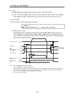
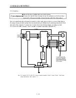
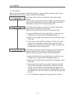
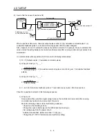
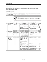
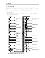
(2) How to find the cause of position shift
Encoder
Q
P
C
M
L
(b) Cumulative command pulses
(c) Cumulative feedback pulses
(d) Machine stop position M
Cause B
(a) Output pulse
counter
Cause A
SON (Servo-on) input
LSP/LSN (Stroke end) input
Servo amplifier
Controller
Servo motor
Machine
Electronic gear
[Pr.PA05], [Pr.PA06],
[Pr.PA07], [Pr.PA21]
Cause C
When a position shift occurs, check (a) output pulse counter Q, (b) cumulative command pulse P, (c)
cumulative feedback pulse C, and (d) machine stop position M in the above diagram.
Also, Causes A, B, and C indicate the causes of position mismatch. For example, Cause A indicates that
noise entered the wiring between the controller and servo amplifier, causing command input pulses to be
miscounted.
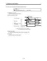
In a normal status without position shift, there are the following relationships.
1) Q = P (Output counter = Cumulative command pulses)
2) When [Pr. PA21] is "0 _ _ _"
P •
CMX [Pr. PA06]
CDV [Pr. PA07]
= C (Cumulative command pulses × Electronic gear = Cumulative feedback
pulses)
3) When [Pr. PA21] is "1 _ _ _"
P •
131072
FBP [Pr. PA05]
= C
4) C •
ǻƐ
= M (Cumulative feedback pulses × Travel distance per pulse = Machine position)
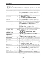
Check for a position mismatch in the following sequence.
1) When Q
P
Noise entered the pulse train signal wiring between the controller and servo amplifier, causing
command input pulses to be miscounted. (Cause A)
Make the following check or take the following measures.
Check how the shielding is done.
Change the open collector type to the differential line driver type.
Run wiring away from the power circuit.
Install a data line filter. (Refer to section 11.9 (2) (a).)
Change the [Pr. PA13 Command pulse input form] setting.
Содержание MELSERVO-JE MR-JE-100A
Страница 23: ...1 FUNCTIONS AND CONFIGURATION 1 12 MEMO ...
Страница 29: ...2 INSTALLATION 2 6 MEMO ...
Страница 91: ...3 SIGNALS AND WIRING 3 62 MEMO ...
Страница 171: ...5 PARAMETERS 5 44 MEMO ...
Страница 195: ...6 NORMAL GAIN ADJUSTMENT 6 24 MEMO ...
Страница 221: ...7 SPECIAL ADJUSTMENT FUNCTIONS 7 26 MEMO ...
Страница 249: ...8 TROUBLESHOOTING 8 28 MEMO ...
Страница 254: ...9 DIMENSIONS 9 5 2 SCR connector system 3M Receptacle 36210 0100PL Shell kit 36310 3200 008 Unit mm 34 8 39 5 22 4 11 0 ...
Страница 255: ...9 DIMENSIONS 9 6 MEMO ...
Страница 263: ...10 CHARACTERISTICS 10 8 MEMO ...
Страница 293: ...11 OPTIONS AND PERIPHERAL EQUIPMENT 11 30 MEMO ...