


APPENDIX
App. - 10
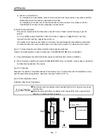
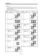
App. 3 Analog monitor
POINT
A voltage of analog monitor output may be irregular at power-on.
The servo status can be outputted to two channels in terms of voltage.
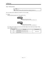
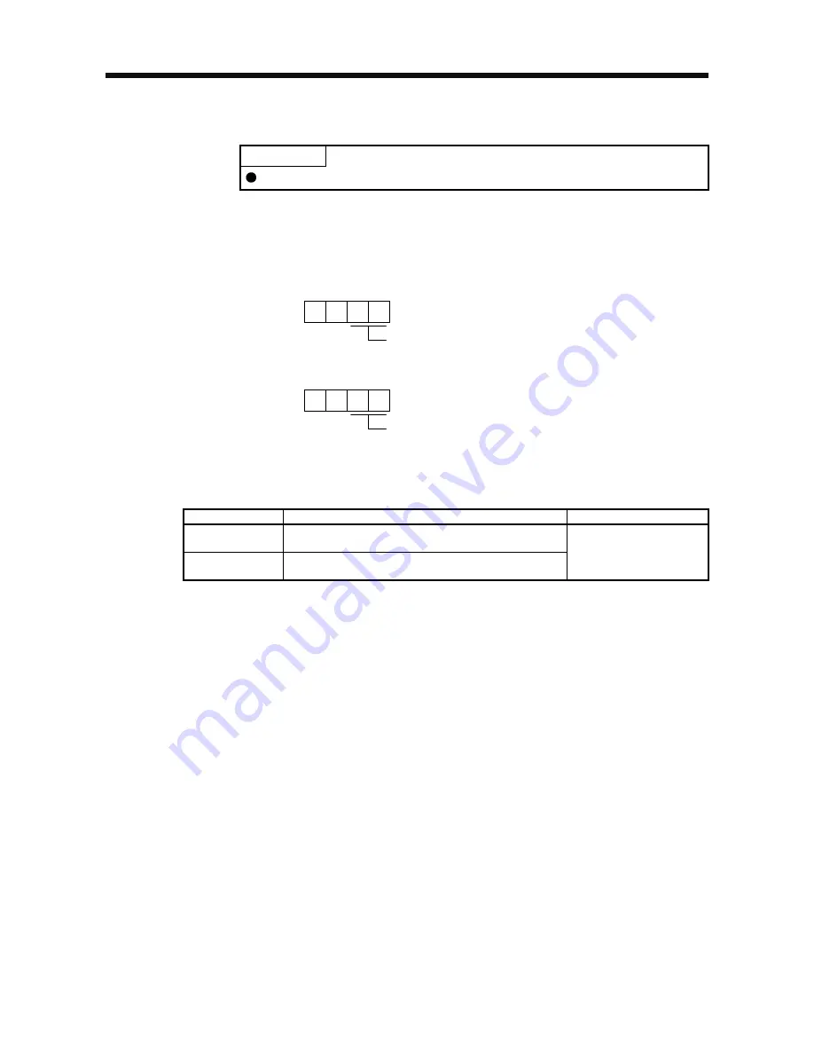
(1) Setting
Change the following digits of [Pr. PC14] and [Pr. PC15].
Analog monitor 1 output selection
(the signal provided to the output across MO1 and LG)
0 0
[Pr. PC14]
Analog monitor 2 output selection
(the signal provided to the output across MO2 and LG)
0 0
[Pr. PC15]
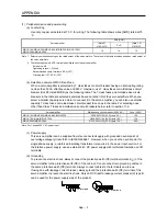
[Pr. PC39] and [Pr. PC40] can be used to set the offset voltages to the analog output voltages. Setting
value is -9999 mV to 9999 mV.
Parameter
Description
Setting range [mV]
PC39
This is used to set the offset voltage of MO1
(Analog monitor 1).
PC40
This is used to set the offset voltage of MO2
(Analog monitor 2).
-9999 to 9999
Содержание MELSERVO-JE MR-JE-100A
Страница 23: ...1 FUNCTIONS AND CONFIGURATION 1 12 MEMO ...
Страница 29: ...2 INSTALLATION 2 6 MEMO ...
Страница 91: ...3 SIGNALS AND WIRING 3 62 MEMO ...
Страница 171: ...5 PARAMETERS 5 44 MEMO ...
Страница 195: ...6 NORMAL GAIN ADJUSTMENT 6 24 MEMO ...
Страница 221: ...7 SPECIAL ADJUSTMENT FUNCTIONS 7 26 MEMO ...
Страница 249: ...8 TROUBLESHOOTING 8 28 MEMO ...
Страница 254: ...9 DIMENSIONS 9 5 2 SCR connector system 3M Receptacle 36210 0100PL Shell kit 36310 3200 008 Unit mm 34 8 39 5 22 4 11 0 ...
Страница 255: ...9 DIMENSIONS 9 6 MEMO ...
Страница 263: ...10 CHARACTERISTICS 10 8 MEMO ...
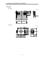
Страница 293: ...11 OPTIONS AND PERIPHERAL EQUIPMENT 11 30 MEMO ...


