7. SPECIAL ADJUSTMENT FUNCTIONS
7 - 17
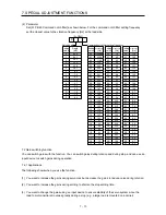
(c) [Pr. PB29 Load to motor inertia ratio after gain switching]
Set the load to motor inertia ratio after gain switching. If the load to motor inertia ratio does not
change, set it to the same value as [Pr. PB06 Load to motor inertia ratio].
(d) [Pr. PB30 Position loop gain after gain switching], [Pr. PB31 Speed loop gain after gain switching],
and [Pr. PB32 Speed integral compensation after gain switching]
Set the values of after switching position loop gain, speed loop gain and speed integral
compensation.
(e) Vibration suppression control after gain switching ([Pr. PB33] to [Pr. PB36]/[Pr. PB56] to [Pr.
PB59])/[Pr. PB60 Model loop gain after gain switching]
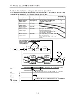
The gain switching vibration suppression control and model loop gain are used only with input device
(CDP) on/off.
You can switch the vibration frequency, resonance frequency, vibration frequency damping,
resonance frequency damping, and model loop gain of the vibration suppression control 1 and
vibration suppression control 2.
7.2.4 Gain switching procedure
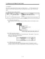
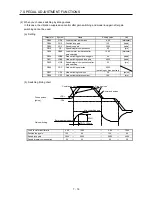
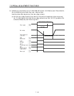
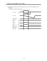
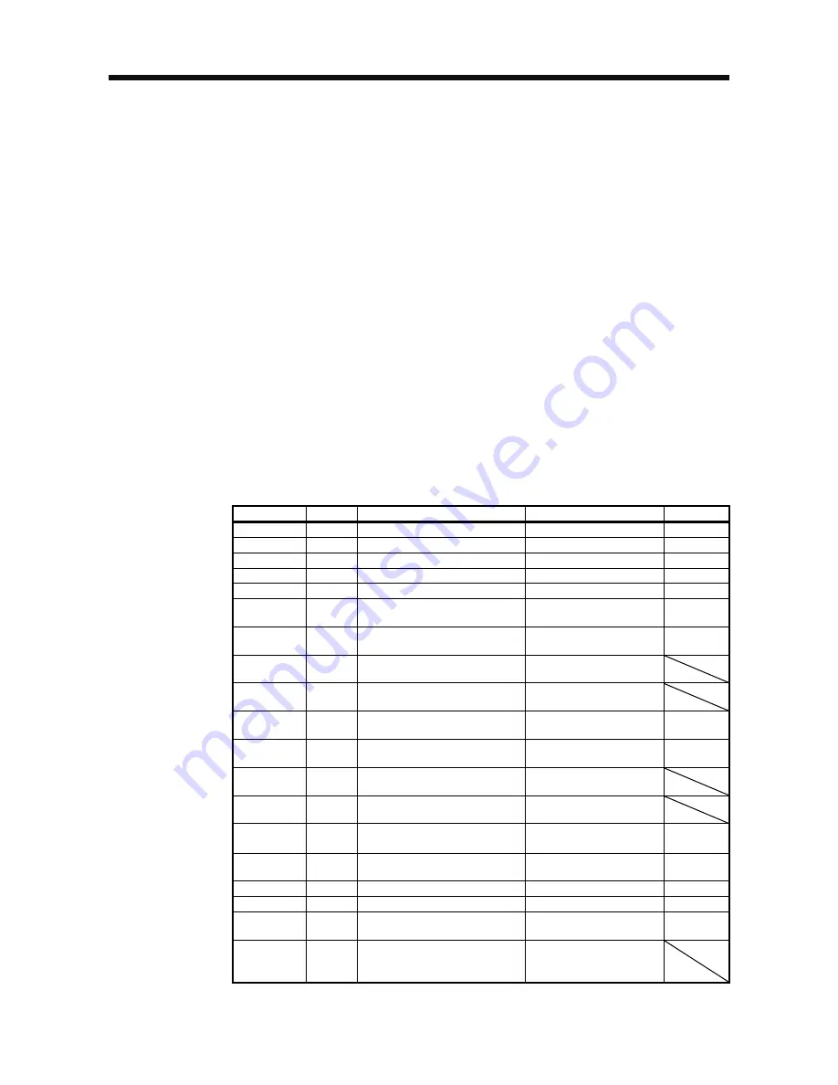
This operation will be described by way of setting examples.
(1) When you choose switching by input device (CDP)
(a) Setting
Parameter
Symbol
Name
Setting value
Unit
PB06
GD2
Load to motor inertia ratio
4.00
[Multiplier]
PB07
PG1
Model loop gain
100
[rad/s]
PB08
PG2
Position loop gain
120
[rad/s]
PB09
VG2
Speed loop gain
3000
[rad/s]
PB10
VIC
Speed integral compensation
20
[ms]
PB19
VRF11 Vibration suppression control 1 -
Vibration frequency
50
[Hz]
PB20
VRF12 Vibration suppression control 1 -
Resonance frequency
50
[Hz]
PB21
VRF13 Vibration suppression control 1 -
Vibration frequency damping
0.20
PB22
VRF14 Vibration suppression control 1 -
Resonance frequency damping
0.20
PB52
VRF21 Vibration suppression control 2 -
Vibration frequency
20
[Hz]
PB53
VRF22 Vibration suppression control 2 -
Resonance frequency
20
[Hz]
PB54
VRF23 Vibration suppression control 2 -
Vibration frequency damping
0.10
PB55
VRF24 Vibration suppression control 2 -
Resonance frequency damping
0.10
PB29
GD2B
Gain switching
Load to motor inertia ratio
10.00
[Multiplier]
PB60
PG1B
Model loop gain after gain
switching
50
[rad/s]
PB30
PG2B
Gain switching position loop gain
84
[rad/s]
PB31
VG2B
Gain switching speed loop gain
4000
[rad/s]
PB32
VICB
Speed integral compensation after
gain switching
50
[ms]
PB26
CDP
Gain switching function
0001
(Switch by input device
(CDP) on/off.)
Содержание MELSERVO-JE MR-JE-100A
Страница 23: ...1 FUNCTIONS AND CONFIGURATION 1 12 MEMO ...
Страница 29: ...2 INSTALLATION 2 6 MEMO ...
Страница 91: ...3 SIGNALS AND WIRING 3 62 MEMO ...
Страница 171: ...5 PARAMETERS 5 44 MEMO ...
Страница 195: ...6 NORMAL GAIN ADJUSTMENT 6 24 MEMO ...
Страница 221: ...7 SPECIAL ADJUSTMENT FUNCTIONS 7 26 MEMO ...
Страница 249: ...8 TROUBLESHOOTING 8 28 MEMO ...
Страница 254: ...9 DIMENSIONS 9 5 2 SCR connector system 3M Receptacle 36210 0100PL Shell kit 36310 3200 008 Unit mm 34 8 39 5 22 4 11 0 ...
Страница 255: ...9 DIMENSIONS 9 6 MEMO ...
Страница 263: ...10 CHARACTERISTICS 10 8 MEMO ...
Страница 293: ...11 OPTIONS AND PERIPHERAL EQUIPMENT 11 30 MEMO ...

