APPENDIX
App. - 2
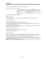
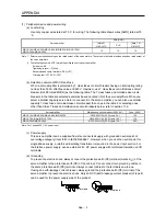
(1) Peripheral device and power wiring
(a) Local wiring
Use only copper wires rated at 75
˚
C for wiring. The following table shows wires [AWG] rated at 75
˚
C.
Wire [AWG]
Servo amplifier
(Note 2)
L1/L2/L3/
P+/C
(Note 1, 2)
U/V/W/
MR-JE-10A/MR-JE-20A/MR-JE-40A/MR-JE-70A/MR-JE-100A/
MR-JE-200A/MR-JE-300A
14
14
14
Note 1. Select wire sizes depending on the rated output of the servo motors. The values in the table are sizes based on rated output of
the servo amplifiers.
2. The following shows the PE terminal specifications of the servo amplifier.
Screw size: M4
Tightening torque: 1.2 [N•m]
Recommended crimp terminals: R2-4 (JST)
Crimping tool: YPT-60-21 (JST)
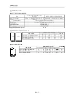
(b) Selection example of MCCB and fuse
When a servo amplifier is protected by T class fuses or circuit breaker having an interrupting rating
not less than 300 A effective value and 240 V maximum, use T class fuses or molded-case circuit
breaker (UL489 Listed MCCB) as the following table. The T class fuses and molded-case circuit
breakers in the table are selected examples based on rated I/O of the servo amplifiers. When you
select a smaller capacity servo motor to connect it to the servo amplifier, you can also use smaller
capacity T class fuses or molded-case circuit breaker than ones in the table. For selecting ones
other than Class T fuses and molded-case circuit breakers below, refer to section 11.6.
Servo amplifier
Molded-case circuit breaker (240 V AC)
Fuse (300 V)
MR-JE-10A/MR-JE-20A/MR-JE-40A/MR-JE-70A
NF50-SWU-5A (50 A frame 5 A)
10 A
MR-JE-70A (Note)/MR-JE-100A
NF50-SWU-10A (50 A frame 10 A)
15 A
MR-JE-200A/MR-JE-300A
NF50-SWU-15A (50 A frame 15 A)
30 A
Note. For 1-phase 200 V AC power input
(c) Power supply
This servo amplifier can be supplied from star-connected supply with grounded neutral point of
overvoltage category III set forth in IEC/EN 60664-1. However, when you use the neutral point for
single phase supply, a reinforced insulating transformer is required in the power input section. For
the interface power supply, use an external 24 V DC power supply with reinforced insulation on I/O
terminals.
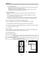
(d) Grounding
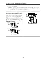
To prevent an electric shock, always connect the protective earth (PE) terminal (marked ) of the
servo amplifier to the protective earth (PE) of the cabinet. Do not connect two grounding cables to
the same protective earth (PE) terminal. Always connect cables to the terminals one-to-one.
If using an earth-leakage current breaker, always ground the protective earth (PE) terminal of the
servo amplifier to prevent an electric shock. Only an RCD (earth-leakage current breaker) of type B
can be used for the power supply side of the product.
PE terminals
PE terminals
Содержание MELSERVO-JE MR-JE-100A
Страница 23: ...1 FUNCTIONS AND CONFIGURATION 1 12 MEMO ...
Страница 29: ...2 INSTALLATION 2 6 MEMO ...
Страница 91: ...3 SIGNALS AND WIRING 3 62 MEMO ...
Страница 171: ...5 PARAMETERS 5 44 MEMO ...
Страница 195: ...6 NORMAL GAIN ADJUSTMENT 6 24 MEMO ...
Страница 221: ...7 SPECIAL ADJUSTMENT FUNCTIONS 7 26 MEMO ...
Страница 249: ...8 TROUBLESHOOTING 8 28 MEMO ...
Страница 254: ...9 DIMENSIONS 9 5 2 SCR connector system 3M Receptacle 36210 0100PL Shell kit 36310 3200 008 Unit mm 34 8 39 5 22 4 11 0 ...
Страница 255: ...9 DIMENSIONS 9 6 MEMO ...
Страница 263: ...10 CHARACTERISTICS 10 8 MEMO ...
Страница 293: ...11 OPTIONS AND PERIPHERAL EQUIPMENT 11 30 MEMO ...

