APPENDIX
App. - 5
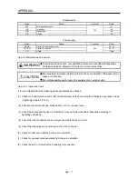
App. 2.3 Electrical Installation and configuration diagram
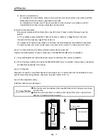
WARNING
Turn off the molded-case circuit breaker (MCCB) to avoid electrical shocks or
damages to the product before starting the installation or wiring.
CAUTION
Connecting a servo motor of the wrong axis to U, V, W, or CN2 of the servo
amplifier may cause a malfunction.
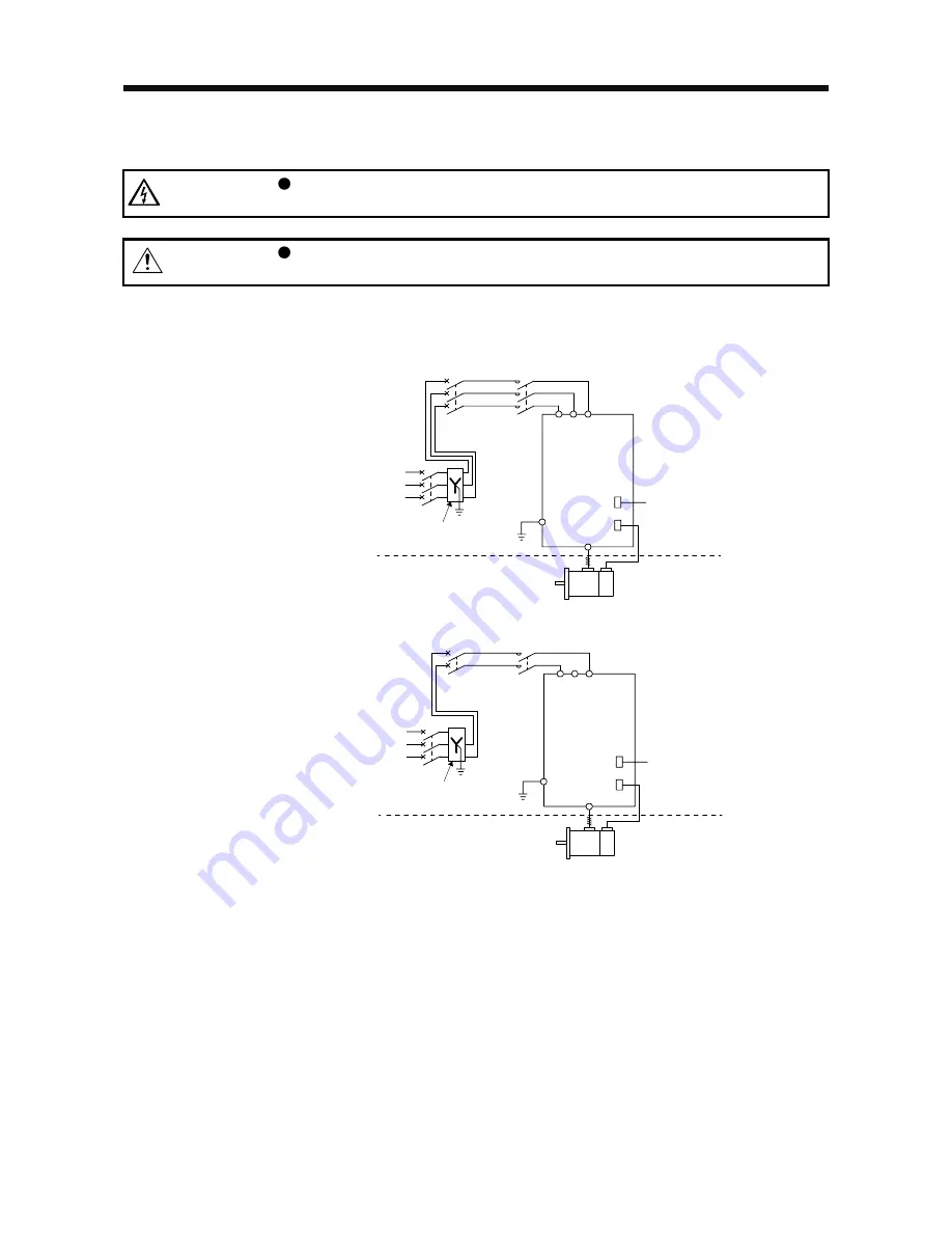
The following shows representative configuration examples to conform to the IEC/EN/UL/CSA standards.
(1) 3-phase input
MCCB
or fuse
Controller
Encoder cable
(3-phase
230 V AC)
Power
supply
(3-phase
400 V AC)
Transformer
(star-connected)
PE
MC
Servo amplifier
Cabinet side
Machine side
Encoder
Servo motor
L1
U/V/W/PE
CN2
CN1
L2 L3
(2) 1-phase input
MCCB
or fuse
Controller
Encoder cable
(3-phase
230 V AC)
Power
supply
(3-phase
400 V AC)
Transformer
(star-connected)
PE
MC
Servo amplifier
Cabinet side
Machine side
Encoder
Servo motor
L1
U/V/W/PE
CN2
CN1
L2 L3
The control circuit connectors described by rectangles are safely separated from the main circuits described
by circles.
The connected motors will be limited as follows.
HF-KN/HF-SN series servo motors (Mfg.: Mitsubishi Electric)
Содержание MELSERVO-JE MR-JE-100A
Страница 23: ...1 FUNCTIONS AND CONFIGURATION 1 12 MEMO ...
Страница 29: ...2 INSTALLATION 2 6 MEMO ...
Страница 91: ...3 SIGNALS AND WIRING 3 62 MEMO ...
Страница 171: ...5 PARAMETERS 5 44 MEMO ...
Страница 195: ...6 NORMAL GAIN ADJUSTMENT 6 24 MEMO ...
Страница 221: ...7 SPECIAL ADJUSTMENT FUNCTIONS 7 26 MEMO ...
Страница 249: ...8 TROUBLESHOOTING 8 28 MEMO ...
Страница 254: ...9 DIMENSIONS 9 5 2 SCR connector system 3M Receptacle 36210 0100PL Shell kit 36310 3200 008 Unit mm 34 8 39 5 22 4 11 0 ...
Страница 255: ...9 DIMENSIONS 9 6 MEMO ...
Страница 263: ...10 CHARACTERISTICS 10 8 MEMO ...
Страница 293: ...11 OPTIONS AND PERIPHERAL EQUIPMENT 11 30 MEMO ...

