


4. STARTUP
4 - 28
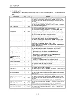
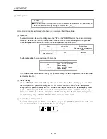
4.5.7 External I/O signal display
POINT
The I/O signal settings can be changed using the I/O setting parameters [Pr.
PD03] to [Pr. PD28].
The on/off states of the digital I/O signals connected to the servo amplifier can be confirmed.
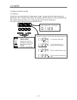
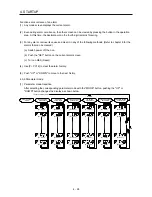
(1) Operation
The display screen at power-on. Using the "MODE" button, display the diagnostic screen.
Press "UP" twice.
…… External I/O signal display screen
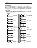
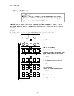
(2) Display definition
The 7-segment LED segments and CN1 connector pins correspond as shown below.
Input signal
Output signals
Always lit
CN1
42
CN1
41
CN1
48
CN1
19
CN1
15
CN1
23
CN1
49
CN1
24
Light on: on
Light off: off
CN1
33
CN1
44
CN1
43
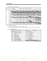
The LED segment corresponding to the pin is lit to indicate on, and is extinguished to indicate off.
The signals corresponding to the pins in the respective control modes are indicated below.
Содержание MELSERVO-JE MR-JE-100A
Страница 23: ...1 FUNCTIONS AND CONFIGURATION 1 12 MEMO ...
Страница 29: ...2 INSTALLATION 2 6 MEMO ...
Страница 91: ...3 SIGNALS AND WIRING 3 62 MEMO ...
Страница 171: ...5 PARAMETERS 5 44 MEMO ...
Страница 195: ...6 NORMAL GAIN ADJUSTMENT 6 24 MEMO ...
Страница 221: ...7 SPECIAL ADJUSTMENT FUNCTIONS 7 26 MEMO ...
Страница 249: ...8 TROUBLESHOOTING 8 28 MEMO ...
Страница 254: ...9 DIMENSIONS 9 5 2 SCR connector system 3M Receptacle 36210 0100PL Shell kit 36310 3200 008 Unit mm 34 8 39 5 22 4 11 0 ...
Страница 255: ...9 DIMENSIONS 9 6 MEMO ...
Страница 263: ...10 CHARACTERISTICS 10 8 MEMO ...
Страница 293: ...11 OPTIONS AND PERIPHERAL EQUIPMENT 11 30 MEMO ...