


3. SIGNALS AND WIRING
3 - 4
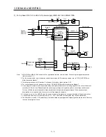
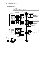
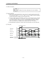
(2) For 1-phase 200 V AC to 240 V AC power supply of MR-JE-10A to MR-JE-70A
POINT
Connect the 1-phase 200 V AC to 240 V AC power supply to L1 and L3. One of
the connecting destinations is different from MR-E Super Series Servo
Amplifier's. When using MR-JE as a replacement for MR-E Super, be careful not
to connect the power to L2.
(Note 5)
MC
ALM
DOCOM
CN1
(Note 3)
24 V DC (Note 8)
24 V DC (Note 8)
Malfunction
RA1
L1
L2
L3
1-phase
200 V AC to
240 V AC
Servo amplifier
U
V
W
(Note 1)
CNP1
Servo motor
U
V
W
M
Motor
Encoder
CN2
(Note 2)
Encoder cable
(Note 4, 7)
CN1
Forced stop 2
Servo-on
(Note 3)
EM2
SON
DICOM
(Note 6)
Power
supply
MCCB
(Note 7)
C
P+
Built-in
regenerative
resistor
RA1
OFF
MC
ON
MC
SK
EMG stop switch
Malfunction
Note 1. MR-JE-40A and MR-JE-70A have a built-in regenerative resistor. (factory-wired) When using the regenerative option,
refer to section 11.2.
2. For the encoder cable, use of the option cable is recommended. For selecting cables, refer to "HF-KN/HF-SN Servo
Motor Instruction Manual".
3. This diagram shows sink I/O interface. For source I/O interface, refer to section 3.9.3.
4. For connecting servo motor power wires, refer to "HF-KN/HF-SN Servo Motor Instruction Manual".
5. Use a magnetic contactor with an operation delay time (interval between current being applied to the coil until closure of
contacts) of 80 ms or less. Depending on the power supply voltage and operation pattern, bus voltage can decrease.
This can shift the mode to the dynamic brake deceleration during forced stop deceleration. When dynamic brake
deceleration is not required, slow the time to turn off the magnetic contactor.
6. Configure a circuit to turn off EM2 when the power is turned off to prevent an unexpected restart of the servo amplifier.
7. Connecting a servo motor of the wrong axis to U, V, W, or CN2 of the servo amplifier may cause a malfunction.
8. The illustration of the 24 V DC power supply is divided between input signal and output signal for convenience. However,
they can be configured by one.
Содержание MELSERVO-JE MR-JE-100A
Страница 23: ...1 FUNCTIONS AND CONFIGURATION 1 12 MEMO ...
Страница 29: ...2 INSTALLATION 2 6 MEMO ...
Страница 91: ...3 SIGNALS AND WIRING 3 62 MEMO ...
Страница 171: ...5 PARAMETERS 5 44 MEMO ...
Страница 195: ...6 NORMAL GAIN ADJUSTMENT 6 24 MEMO ...
Страница 221: ...7 SPECIAL ADJUSTMENT FUNCTIONS 7 26 MEMO ...
Страница 249: ...8 TROUBLESHOOTING 8 28 MEMO ...
Страница 254: ...9 DIMENSIONS 9 5 2 SCR connector system 3M Receptacle 36210 0100PL Shell kit 36310 3200 008 Unit mm 34 8 39 5 22 4 11 0 ...
Страница 255: ...9 DIMENSIONS 9 6 MEMO ...
Страница 263: ...10 CHARACTERISTICS 10 8 MEMO ...
Страница 293: ...11 OPTIONS AND PERIPHERAL EQUIPMENT 11 30 MEMO ...