


17 - 14
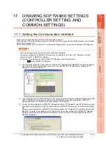
17. DRAWING SOFTWARE SETTINGS (CONTROLLER SETTING AND COMMON SETTINGS)
17.2 Common Settings Dedicated to Handy GOT
POINT
POINT
POINT
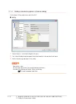
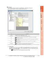
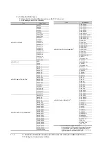
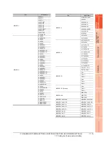
Channel No., drivers
(1) Channel No.2 to No.4
Use the channel No.2 to No.4 when using the Multi-channel function.
For details of the Multi-channel function, refer to the following.
(2) Drivers
The displayed items for a driver differ according to the settings [Manufacturer], [Controller Type] and [I/F].
When the driver to be set is not displayed, confirm if [Manufacturer], [Controller Type] and [I/F] are correct.
[Setting the communication interface] section in each chapter
17.1.3 Precautions
(1) When using the multiple CPU system
When using the GOT to monitor the multiple CPU system of other stations, select [MELSEC-Q(Multi)/Q-Motion]
or [MELSEC-QnU/DC, Q17nD/M/NC/DR, CRnD-700] for the type, regardless of the host PLC CPU type (QCPU,
QnACPU, ACPU).
When other models are selected, the setting of the CPU No. becomes unavailable.
(2) Precautions for changing model
(a) When devices that cannot be converted are included.
When setting of [Manufacturer] or [Controller Type] is changed, GT Designer3 displays the device that
cannot be converted (no corresponding device type, or excessive setting ranges) as [??]. In this case, set
the device again.
(b) When the changed Manufacturer or Controller Type does not correspond to the network.
The network will be set to the host station.
(c) When the Manufacturer or Controller Type is changed to [None]
The GT Designer3 displays the device of the changed channel No. as [??]. In this case, set the device
again.
Since the channel No. is retained, the objects can be reused in other channel No. in a batch by using the
[Device Bach Edit], [CH No. Batch Edit] or [Device List].
17.2 Common Settings Dedicated to Handy GOT
The following data are written as common settings: the system information to control the LED display for the Handy GOT
operation switch and for the grip switch.
After defining the system information and the Handy GOT setting in [Common Settings] of drawing software, write the
common settings to the Handy GOT.
For details on Common Settings, refer to the following manual.
GT Designer3 Version1 Screen Design Manual (Fundamentals)
For the settings on the display LED for operation switch, refer to the following section.
9.4.5 LED setting of operation switch
For the settings on the display LED for grip switch, refer to the following section.
Содержание GT16
Страница 1: ......
Страница 2: ......
Страница 46: ...1 4 1 OVERVIEW 1 1 Features ...
Страница 54: ...2 8 2 SYSTEM CONFIGURATION 2 2 System Equipment ...
Страница 60: ...3 6 3 SPECIFICATIONS 3 4 Battery specifications ...
Страница 72: ...5 8 5 UL cUL STANDARDS AND EMC DIRECTIVE 5 2 EMC Directive ...
Страница 102: ...6 30 6 OPTION 6 7 Connector Conversion Box ...
Страница 106: ...7 4 7 INSTALLATION 7 1 Installing Procedure ...
Страница 110: ...8 4 8 COMMUNICATION CABLE 8 1 Overview of Communication Cable ...
Страница 130: ...9 20 9 HANDLING OF POWER WIRING AND SWITCH 9 4 Switch Wiring ...
Страница 142: ...10 12 10 UTILITY FUNCTION 10 3 Utility Display ...
Страница 184: ...11 42 11 DISPLAY AND OPERATION SETTINGS GOT SET UP 11 4 Maintenance Function ...
Страница 202: ...12 18 12 COMMUNICATION INTERFACE SETTING COMMUNICATION SETTING 12 3 Ethernet Setting ...
Страница 226: ...13 24 13 DEBUG 13 3 Memory Data Control ...
Страница 248: ...14 22 14 SELF CHECK 14 2 Batch Self Check ...
Страница 350: ...15 102 15 DATA CONTROL 15 3 OS Project Information ...
Страница 410: ...19 22 19 TROUBLESHOOTING 19 2 Error Message and System Alarm ...
Страница 418: ...App 8 APPENDICES Appendix 3 Transportation Precautions ...
Страница 422: ...REVISIONS 4 ...
Страница 425: ......
Страница 426: ......
Страница 427: ......
Страница 428: ......
Страница 470: ......
Страница 510: ...21 22 21 COMPUTER LINK CONNECTION 21 6 Precautions ...
Страница 568: ...22 58 22 ETHERNET CONNECTION 22 5 Precautions ...
Страница 584: ......
Страница 626: ...25 14 25 SERVO AMPLIFIER CONNECTION 25 7 Precautions ...
Страница 632: ...26 6 26 ROBOT CONTROLLER CONNECTION 26 6 Precautions ...
Страница 647: ...MULTIPLE GOT CONNECTIONS 29 GOT MULTI DROP CONNECTION 29 1 ...
Страница 648: ......
Страница 659: ...MULTI CHANNEL FUNCTION 30 MULTI CHANNEL FUNCTION 30 1 ...
Страница 660: ......
Страница 675: ...FA TRANSPARENT FUNCTION 31 FA TRANSPARENT FUNCTION 31 1 ...
Страница 676: ......
Страница 742: ...31 66 31 FA TRANSPARENT FUNCTION 31 7 Precautions ...
Страница 744: ......
Страница 766: ...32 22 32 CONNECTION TO IAI ROBOT CONTROLLER 32 7 Precautions ...
Страница 802: ...34 10 34 CONNECTION TO OMRON TEMPERATURE CONTROLLER 34 7 Precautions ...
Страница 834: ...36 18 36 CONNECTION TO KOYO EI PLC 36 6 Device Range that Can Be Set ...
Страница 858: ...38 12 38 CONNECTION TO SHARP PLC 38 6 Device Range that Can Be Set ...
Страница 868: ...39 10 39 CONNECTION TO SHINKO TECHNOS INDICATING CONTROLLER 39 7 Precautions ...
Страница 902: ...42 6 42 CONNECTION TO TOSHIBA MACHINE PLC 42 6 Device Range that Can Be Set ...
Страница 908: ...43 6 43 CONNECTION TO PANASONIC SERVO AMPLIFIER 43 7 Precautions ...
Страница 970: ...48 12 48 CONNECTION TO FUJI TEMPERATURE CONTROLLER 48 7 Precautions ...
Страница 1052: ...52 26 52 CONNECTION TO AZBIL CONTROL EQUIPMENT 52 7 Precautions ...
Страница 1102: ...55 14 55 CONNECTION TO GE PLC 55 7 Precautions ...
Страница 1114: ...57 4 57 CONNECTION TO SICK SAFETY CONTROLLER 57 5 Device Range that Can Be Set ...
Страница 1128: ...59 2 59 CONNECTION TO HIRATA CORPORATION HNC CONTROLLER ...
Страница 1130: ...60 2 60 CONNECTION TO MURATEC CONTROLLER ...
Страница 1131: ...MICROCOMPUTER CONNECTION 61 MICROCOMPUTER CONNECTION SERIAL 61 1 62 MICROCOMPUTER CONNECTION ETHERNET 62 1 ...
Страница 1132: ......
Страница 1270: ...62 68 62 MICROCOMPUTER CONNECTION ETHERNET 62 8 Precautions ...
Страница 1271: ...MODBUS CONNECTIONS 63 MODBUS R RTU CONNECTION 63 1 64 MODBUS R TCP CONNECTION 64 1 ...
Страница 1272: ......
Страница 1292: ...64 12 64 MODBUS R TCP CONNECTION 64 7 Precautions ...
Страница 1293: ...CONNECTIONS TO PERIPHERAL EQUIPMENT 65 VNC R SERVER CONNECTION 65 1 ...
Страница 1294: ......
Страница 1298: ...65 4 65 VNC R SERVER CONNECTION 65 4 Setting in Personal Computer ...
Страница 1302: ...REVISIONS 4 ...
Страница 1305: ......
Страница 1306: ......