


62. MICROCOMPUTER CONNECTION (ETHERNET)
62.4 Message Formats
62 - 13
60
CONNECTION T
O
MURA
T
E
C
CONTROLL
ER
61
MI
C
R
O
C
OMPUTER
CONNECTION
(SE
R
IA
L)
62
MICR
OCOMPUTER
CONNECTION
(E
T
HE
RN
E
T)
63
MO
D
B
US(R)/
R
T
U
CONNE
C
T
ION
64
MO
DBUS(R)/
TCP
CON
N
E
C
T
ION
65
V
NC(R) S
E
R
V
E
R
CONNECTION
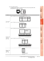
62.4 Message Formats
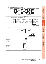
This section describes the format of messages that can be used in the microcomputer connection (Ethernet).
62.4.1 Data format type and application
Data format type and application
Communication is possible using any of the data formats shown below.
(1) Formats 1, 2 (GOT-A900 Series microcomputer connection)
This is the compatible message format with when a microcomputer connection is established with the GOT-
A900 Series.
(2) Formats 3, 4 (GOT-F900 Series microcomputer connection)
This is the compatible message format with when a microcomputer connection is established with the GOT-
F900 Series.
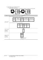
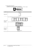
(3) Format 5 (Digital Electronics Corporation's memory link method)
This is the compatible message format with the protocol of the Digital Electronics Corporation's memory link
method.
(4) Formats 6, 7 (4E frame)
This is the compatible message format with when a communication is performed using the MC protocol of Q/
QnA Series serial communication module.
(5) Formats 8, 9 (3E frame)
This is the compatible message format with when a communication is performed using the MC protocol of Q/
QnA Series serial communication module.
How to set data format
Set the data format at [Detail Setting] in GT Designer3.
For details of the data format setting method, refer to the following.
62.5.1 Setting communication interface (Communication settings)
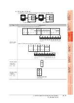
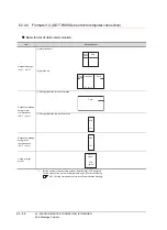
Type
Name
Description
Refer to
Format 1
GOT-A900 series microcomputer connection
(ASCII)
This format is used when the GOT is connected to the host in a 1:1 connection.
The data format is ASCII.
Format 2
GOT-A900 series microcomputer connection
(Binary)
This format is used when the GOT is connected to the host in a 1:1 connection.
The data format is Binary.
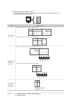
Type
Name
Description
Refer to
Format 3
GOT-F900 series microcomputer connection
(ASCII)
Use this format when establishing a 1:1 or m:n connection between the
GOT and the host.
The data format is ASCII.
Format 4
GOT-F900 series microcomputer connection
(Binary)
Use this format when establishing a 1:1 or m:n connection between the
GOT and the host.
The data format is Binary.
Type
Name
Description
Refer to
Format 5
Digital Electronics Corporation's memory link
method
This is the basic format of the Digital Electronics Corporation's memory link
method.
Type
Name
Description
Refer to
Format 6
4E frame (ASCII)
This is the basic format of the MC protocols. The data format is ASCII.
Format 7
4E frame (Binary)
This is the basic format of the MC protocols. The data format is Binary.
Type
Name
Description
Refer to
Format 8
3E frame (ASCII)
This is the basic format of the MC protocols. The data format is ASCII.
Format 9
3E frame (Binary)
This is the basic format of the MC protocols. The data format is Binary.
Содержание GT16
Страница 1: ......
Страница 2: ......
Страница 46: ...1 4 1 OVERVIEW 1 1 Features ...
Страница 54: ...2 8 2 SYSTEM CONFIGURATION 2 2 System Equipment ...
Страница 60: ...3 6 3 SPECIFICATIONS 3 4 Battery specifications ...
Страница 72: ...5 8 5 UL cUL STANDARDS AND EMC DIRECTIVE 5 2 EMC Directive ...
Страница 102: ...6 30 6 OPTION 6 7 Connector Conversion Box ...
Страница 106: ...7 4 7 INSTALLATION 7 1 Installing Procedure ...
Страница 110: ...8 4 8 COMMUNICATION CABLE 8 1 Overview of Communication Cable ...
Страница 130: ...9 20 9 HANDLING OF POWER WIRING AND SWITCH 9 4 Switch Wiring ...
Страница 142: ...10 12 10 UTILITY FUNCTION 10 3 Utility Display ...
Страница 184: ...11 42 11 DISPLAY AND OPERATION SETTINGS GOT SET UP 11 4 Maintenance Function ...
Страница 202: ...12 18 12 COMMUNICATION INTERFACE SETTING COMMUNICATION SETTING 12 3 Ethernet Setting ...
Страница 226: ...13 24 13 DEBUG 13 3 Memory Data Control ...
Страница 248: ...14 22 14 SELF CHECK 14 2 Batch Self Check ...
Страница 350: ...15 102 15 DATA CONTROL 15 3 OS Project Information ...
Страница 410: ...19 22 19 TROUBLESHOOTING 19 2 Error Message and System Alarm ...
Страница 418: ...App 8 APPENDICES Appendix 3 Transportation Precautions ...
Страница 422: ...REVISIONS 4 ...
Страница 425: ......
Страница 426: ......
Страница 427: ......
Страница 428: ......
Страница 470: ......
Страница 510: ...21 22 21 COMPUTER LINK CONNECTION 21 6 Precautions ...
Страница 568: ...22 58 22 ETHERNET CONNECTION 22 5 Precautions ...
Страница 584: ......
Страница 626: ...25 14 25 SERVO AMPLIFIER CONNECTION 25 7 Precautions ...
Страница 632: ...26 6 26 ROBOT CONTROLLER CONNECTION 26 6 Precautions ...
Страница 647: ...MULTIPLE GOT CONNECTIONS 29 GOT MULTI DROP CONNECTION 29 1 ...
Страница 648: ......
Страница 659: ...MULTI CHANNEL FUNCTION 30 MULTI CHANNEL FUNCTION 30 1 ...
Страница 660: ......
Страница 675: ...FA TRANSPARENT FUNCTION 31 FA TRANSPARENT FUNCTION 31 1 ...
Страница 676: ......
Страница 742: ...31 66 31 FA TRANSPARENT FUNCTION 31 7 Precautions ...
Страница 744: ......
Страница 766: ...32 22 32 CONNECTION TO IAI ROBOT CONTROLLER 32 7 Precautions ...
Страница 802: ...34 10 34 CONNECTION TO OMRON TEMPERATURE CONTROLLER 34 7 Precautions ...
Страница 834: ...36 18 36 CONNECTION TO KOYO EI PLC 36 6 Device Range that Can Be Set ...
Страница 858: ...38 12 38 CONNECTION TO SHARP PLC 38 6 Device Range that Can Be Set ...
Страница 868: ...39 10 39 CONNECTION TO SHINKO TECHNOS INDICATING CONTROLLER 39 7 Precautions ...
Страница 902: ...42 6 42 CONNECTION TO TOSHIBA MACHINE PLC 42 6 Device Range that Can Be Set ...
Страница 908: ...43 6 43 CONNECTION TO PANASONIC SERVO AMPLIFIER 43 7 Precautions ...
Страница 970: ...48 12 48 CONNECTION TO FUJI TEMPERATURE CONTROLLER 48 7 Precautions ...
Страница 1052: ...52 26 52 CONNECTION TO AZBIL CONTROL EQUIPMENT 52 7 Precautions ...
Страница 1102: ...55 14 55 CONNECTION TO GE PLC 55 7 Precautions ...
Страница 1114: ...57 4 57 CONNECTION TO SICK SAFETY CONTROLLER 57 5 Device Range that Can Be Set ...
Страница 1128: ...59 2 59 CONNECTION TO HIRATA CORPORATION HNC CONTROLLER ...
Страница 1130: ...60 2 60 CONNECTION TO MURATEC CONTROLLER ...
Страница 1131: ...MICROCOMPUTER CONNECTION 61 MICROCOMPUTER CONNECTION SERIAL 61 1 62 MICROCOMPUTER CONNECTION ETHERNET 62 1 ...
Страница 1132: ......
Страница 1270: ...62 68 62 MICROCOMPUTER CONNECTION ETHERNET 62 8 Precautions ...
Страница 1271: ...MODBUS CONNECTIONS 63 MODBUS R RTU CONNECTION 63 1 64 MODBUS R TCP CONNECTION 64 1 ...
Страница 1272: ......
Страница 1292: ...64 12 64 MODBUS R TCP CONNECTION 64 7 Precautions ...
Страница 1293: ...CONNECTIONS TO PERIPHERAL EQUIPMENT 65 VNC R SERVER CONNECTION 65 1 ...
Страница 1294: ......
Страница 1298: ...65 4 65 VNC R SERVER CONNECTION 65 4 Setting in Personal Computer ...
Страница 1302: ...REVISIONS 4 ...
Страница 1305: ......
Страница 1306: ......