


53 - 20
53. CONNECTION TO RKC TEMPERATURE CONTROLLER
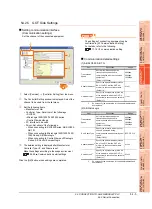
53.5 Temperature Controller Side Setting
53.5.7 Connecting to RB Series
Communication settings
*1
When the setting value is set to 0, a communication is not
made.
*2
Adjust the settings with GOT settings.
Data bit configuration
Communication setting mode
Set the communication setting mode using the
operation panel of the RB series main unit.
For details of the communication setting mode, refer to
the following.
RB series "Communication Instruction Manual"
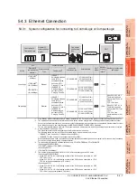
53.5.8 Connecting to PF900
Communication settings
Make the communication settings by operating the key
of the temperature controller.
*1
Adjust the settings with GOT settings.
*2
Select the device address1 without overlapping with that of
other units.
*3
Set the maximum time from the sending of the last character
stop bit from the GOT side until the switching of the GOT
side to the receiving status (until the temperature controller
becomes ready to send). Set as necessary.
*4
When the setting value is set to 0, a communication is not
made.
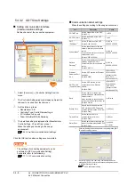
53.5.9 Connecting to HA400, HA900
Communication settings
Make the communication settings by operating the key
of the temperature controller.
(Communication 1)
(Communication 2)
*1
Adjust the settings with GOT settings.
*2
Select the device address1/2 without overlapping with that of
other units.
*3
Set the maximum time from the sending of the last character
stop bit from the GOT side until the switching of the GOT
side to the receiving status (until the temperature controller
becomes ready to send). Set as necessary.
*4
When the setting value is set to 0, a communication is not made.
53.5.10 Connecting to AG500
Communication settings
Make the communication settings by operating the key
of the temperature controller.
*1
Adjust the settings with GOT settings.
*2
Select the device address1 without overlapping with that of
other units.
*3
Set the maximum time from the sending of the last character
stop bit from the GOT side until the switching of the GOT
side to the receiving status (until the temperature controller
becomes ready to send). Set as necessary.
*4
When the setting value is set to 0, a communication is not made.
Item
Setting range
Communication protocol
1: MODBUS
Device address
(Slave address)
*1
1 to 99
Communication speed
*2
2: 9600bps
3: 19200bps
Data bit configuration
Refer to
■
Interval time
0 to 250
Set value
Data bit
Parity bit
Stop bit
0
8
None
1
1
8
None
2
2
8
Even
1
3
8
Even
2
4
8
Odd
1
5
8
Odd
2
Item
Setting range
Communication speed1
*1
9600bps, 19200bps, 38400bps,
57600bps
Communication protocol1
MODBUS
Data bit configuration1
*1
(Data bit, Parity bit, Stop bit)
[8N1]: 8bit, None, 1bit
[8N2]: 8bit, None, 2bit
[8E1]: 8bit, Even, 1bit
[8E2]: 8bit, Even, 2bit
[8O1]: 8bit, Odd, 1bit
[8O2]: 8bit, Odd, 2bit
Device address1
*2
(Slave address1)
1 to 99
*4
Interval time
*3
0 to 250 (ms)
Item
Setting range
Communication speed1
*1
9600bps, 19200bps, 38400bps
Data bit configuration1
*1
(Data bit, Parity bit, Stop bit)
[8N1]: 8bit, None, 1bit
[8N2]: 8bit, None, 2bit
[8E1]: 8bit, Even, 1bit
[8E2]: 8bit, Even, 2bit
[8O1]: 8bit, Odd, 1bit
[8O2]: 8bit, Odd, 2bit
Device address1
*2
(Slave address1)
1 to 99
*4
Interval time
*3
0 to 250 (ms)
Item
Setting range
Communication speed2
*1
9600bps, 19200bps, 38400bps
Data bit configuration2
*1
(Data bit, Parity bit, Stop bit)
[8N1]: 8bit, None, 1bit
[8N2]: 8bit, None, 2bit
[8E1]: 8bit, Even, 1bit
[8E2]: 8bit, Even, 2bit
[8O1]: 8bit, Odd, 1bit
[8O2]: 8bit, Odd, 2bit
Device address2
*2
(Slave address2)
1 to 99
*4
Interval time
*3
0 to 250 (ms)
Item
Setting range
Communication speed
*1
9600bps, 19200bps, 38400bps
Communication protocol
MODBUS
Data bit configuration
*1
(Data bit, Parity bit, Stop bit)
[8N1]: 8bit, None, 1bit
[8N2]: 8bit, None, 2bit
[8E1]: 8bit, Even, 1bit
[8E2]: 8bit, Even, 2bit
[8O1]: 8bit, Odd, 1bit
[8O2]: 8bit, Odd, 2bit
Device address
*2
(Slave address)
1 to 99
*4
Interval time
*3
0 to 250 (ms)
Содержание GT16
Страница 1: ......
Страница 2: ......
Страница 46: ...1 4 1 OVERVIEW 1 1 Features ...
Страница 54: ...2 8 2 SYSTEM CONFIGURATION 2 2 System Equipment ...
Страница 60: ...3 6 3 SPECIFICATIONS 3 4 Battery specifications ...
Страница 72: ...5 8 5 UL cUL STANDARDS AND EMC DIRECTIVE 5 2 EMC Directive ...
Страница 102: ...6 30 6 OPTION 6 7 Connector Conversion Box ...
Страница 106: ...7 4 7 INSTALLATION 7 1 Installing Procedure ...
Страница 110: ...8 4 8 COMMUNICATION CABLE 8 1 Overview of Communication Cable ...
Страница 130: ...9 20 9 HANDLING OF POWER WIRING AND SWITCH 9 4 Switch Wiring ...
Страница 142: ...10 12 10 UTILITY FUNCTION 10 3 Utility Display ...
Страница 184: ...11 42 11 DISPLAY AND OPERATION SETTINGS GOT SET UP 11 4 Maintenance Function ...
Страница 202: ...12 18 12 COMMUNICATION INTERFACE SETTING COMMUNICATION SETTING 12 3 Ethernet Setting ...
Страница 226: ...13 24 13 DEBUG 13 3 Memory Data Control ...
Страница 248: ...14 22 14 SELF CHECK 14 2 Batch Self Check ...
Страница 350: ...15 102 15 DATA CONTROL 15 3 OS Project Information ...
Страница 410: ...19 22 19 TROUBLESHOOTING 19 2 Error Message and System Alarm ...
Страница 418: ...App 8 APPENDICES Appendix 3 Transportation Precautions ...
Страница 422: ...REVISIONS 4 ...
Страница 425: ......
Страница 426: ......
Страница 427: ......
Страница 428: ......
Страница 470: ......
Страница 510: ...21 22 21 COMPUTER LINK CONNECTION 21 6 Precautions ...
Страница 568: ...22 58 22 ETHERNET CONNECTION 22 5 Precautions ...
Страница 584: ......
Страница 626: ...25 14 25 SERVO AMPLIFIER CONNECTION 25 7 Precautions ...
Страница 632: ...26 6 26 ROBOT CONTROLLER CONNECTION 26 6 Precautions ...
Страница 647: ...MULTIPLE GOT CONNECTIONS 29 GOT MULTI DROP CONNECTION 29 1 ...
Страница 648: ......
Страница 659: ...MULTI CHANNEL FUNCTION 30 MULTI CHANNEL FUNCTION 30 1 ...
Страница 660: ......
Страница 675: ...FA TRANSPARENT FUNCTION 31 FA TRANSPARENT FUNCTION 31 1 ...
Страница 676: ......
Страница 742: ...31 66 31 FA TRANSPARENT FUNCTION 31 7 Precautions ...
Страница 744: ......
Страница 766: ...32 22 32 CONNECTION TO IAI ROBOT CONTROLLER 32 7 Precautions ...
Страница 802: ...34 10 34 CONNECTION TO OMRON TEMPERATURE CONTROLLER 34 7 Precautions ...
Страница 834: ...36 18 36 CONNECTION TO KOYO EI PLC 36 6 Device Range that Can Be Set ...
Страница 858: ...38 12 38 CONNECTION TO SHARP PLC 38 6 Device Range that Can Be Set ...
Страница 868: ...39 10 39 CONNECTION TO SHINKO TECHNOS INDICATING CONTROLLER 39 7 Precautions ...
Страница 902: ...42 6 42 CONNECTION TO TOSHIBA MACHINE PLC 42 6 Device Range that Can Be Set ...
Страница 908: ...43 6 43 CONNECTION TO PANASONIC SERVO AMPLIFIER 43 7 Precautions ...
Страница 970: ...48 12 48 CONNECTION TO FUJI TEMPERATURE CONTROLLER 48 7 Precautions ...
Страница 1052: ...52 26 52 CONNECTION TO AZBIL CONTROL EQUIPMENT 52 7 Precautions ...
Страница 1102: ...55 14 55 CONNECTION TO GE PLC 55 7 Precautions ...
Страница 1114: ...57 4 57 CONNECTION TO SICK SAFETY CONTROLLER 57 5 Device Range that Can Be Set ...
Страница 1128: ...59 2 59 CONNECTION TO HIRATA CORPORATION HNC CONTROLLER ...
Страница 1130: ...60 2 60 CONNECTION TO MURATEC CONTROLLER ...
Страница 1131: ...MICROCOMPUTER CONNECTION 61 MICROCOMPUTER CONNECTION SERIAL 61 1 62 MICROCOMPUTER CONNECTION ETHERNET 62 1 ...
Страница 1132: ......
Страница 1270: ...62 68 62 MICROCOMPUTER CONNECTION ETHERNET 62 8 Precautions ...
Страница 1271: ...MODBUS CONNECTIONS 63 MODBUS R RTU CONNECTION 63 1 64 MODBUS R TCP CONNECTION 64 1 ...
Страница 1272: ......
Страница 1292: ...64 12 64 MODBUS R TCP CONNECTION 64 7 Precautions ...
Страница 1293: ...CONNECTIONS TO PERIPHERAL EQUIPMENT 65 VNC R SERVER CONNECTION 65 1 ...
Страница 1294: ......
Страница 1298: ...65 4 65 VNC R SERVER CONNECTION 65 4 Setting in Personal Computer ...
Страница 1302: ...REVISIONS 4 ...
Страница 1305: ......
Страница 1306: ......