8400 StateLine C | Reference manual
System bus "CAN on board"
Process data transfer
452
L
Firmware
≤
11.00 - DMS 8.0 EN - 10/2011
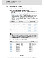
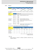
The communication parameters such as the transmission mode and cycle time can be set
freely for every PDO and independently of the settings of other PDOs:
Transmission type
PDO transmission
Logic combination of
different
transmission types
cyclic
synchronous
event-controlled
0
z
z
AND
1 ... 240
z
-
254, 255
z
z
OR
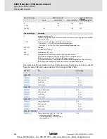
Transmission type
Description
0
Synchronous and acyclic:
The PDO is transmitted on an event-controlled basis with every sync (e.g. when a bit change
occurs in the PDO).
1 ... 240
Synchronous and cyclic (sync-controlled with response):
• Selection n = 1: The PDO is transmitted with every sync.
• Selection 1 < n
≤
240: The PDO is transmitted with every n-th sync.
241 ... 251
Reserved
252
Synchronous - RTR only
253
Asynchronous - RTR only
254, 255
Asynchronous - manufacturer-specific / device profile-specific:
If this value is entered, the PDO transmission is event-controlled or cyclic.
(Note: The values "254" and "255" have the same meaning).
For a cyclic transmission, a cycle time must be entered for the respective PDO. In this case,
cyclic transmission takes place in addition to event-controlled transmission.
Parameter
Info
Lenze setting
Value Unit
CAN1_OUT
C00322/1
Transmission mode
254
C00324/2
Blocking time
0 ms
C00356/5
Cycle time
0 ms
C00358/1
Data length
8 Byte
CAN2_OUT
C00322/2
Transmission mode
254
C00324/3
Blocking time
0 ms
C00356/2
Cycle time
0 ms
C00358/2
Data length
8 Byte
CAN3_OUT
C00322/3
Transmission mode
254
C00324/4
Blocking time
0 ms
C00356/3
Cycle time
0 ms
C00358/3
Data length
8 Byte
CAN1_IN ... CAN3_IN
C00323/1...3
Transmission mode CAN1_IN ... CAN3_IN
• In the case of the RPDO serves as
monitoring setting in the case of sync-
controlled PDOs.
254
Phone: 800.894.0412 - Fax: 888.723.4773 - Web: www.clrwtr.com - Email: [email protected]


