background image

8400 StateLine C | Reference manual

Parameter reference

Parameter list | C00400

592

L

Firmware 

 11.00 - DMS 8.0 EN - 10/2011


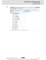
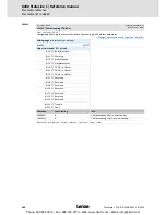
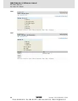
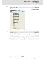
C00400

C00401

C00408

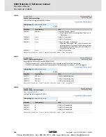
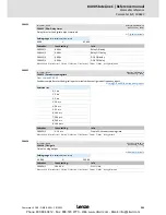
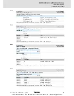
Parameter | Name:

C00400 | LS_PulseGenerator

Data type: UNSIGNED_16

Index: 24175

d

 = 5E6F

h

Time setting of the pulse to be output by the SB 

LS_PulseGenerator

Setting range 

(min. value | unit | max. value)

0

ms

60000

Subcodes

Lenze setting

Info

C00400/1

1000 ms

Length of LOW level (break)

C00400/2

1000 ms

Length of HIGH level

C00400/3

100 ms

From version 06.00.00

Delay time for status signal 

bFirstCycleDone

  • The 

bFirstCycleDone

 status signal is set to TRUE when 

the first task cycle is complete and the time set here 

has expired.

;

Read access

;

Write access

…

CINH

…

PLC STOP

…

No transfer

…

COM

…

MOT

Scaling factor: 1

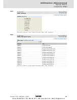
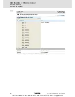
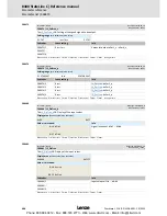
Parameter | Name:

C00401 | CANxInOut: Inversion

Data type: UNSIGNED_16

Index: 24174

d

 = 5E6E

h

From version 03.00.00

This parameter serves to invert the control/status bits of the CAN port blocks.

CAN port block

Setting range 

(min. hex value | max. hex value)

0x0000

0xFFFF

Value is bit-coded:

Info

Bit 0 Active

Bit set = bit is inverted

... ...

Bit 15 Active

Subcodes

Lenze setting

Info

C00401/1

0

Inversion of LP_CanIn1.bCtrl1_B0...15

C00401/2

0

Inversion of LP_CanOut1.bState1_B0...15

C00401/3

0

Inversion of LP_CanIn2.bIn1_B0...15

C00401/4

0

Inversion of LP_CanOut2.bOut1_B0...15

C00401/5

0

Inversion of LP_CanIn3.bIn1_B0...15

C00401/6

0

Inversion of LP_CanOut3.bOut1_B0...15

;

Read access

;

Write access

…

CINH

…

PLC STOP

…

No transfer

…

COM

…

MOT

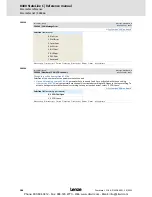
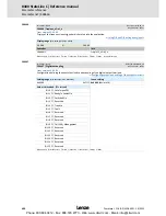
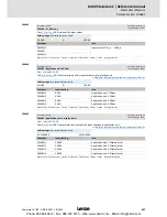
Parameter | Name:

C00408 | LP_CanIn mapping selection

Data type: UNSIGNED_8

Index: 24167

d

 = 5E67

h

From version 03.00.00

Selection of the mapping source for port blocks LP_CanIn1...3

CAN port block

Selection list

Info

0 CanIn

CanIn

1 Par.C409

Mapping configured in 

C00409

Subcodes

Lenze setting

Info

C00408/1

0: CanIn

Mapping selection LP_CanIn1

C00408/2

0: CanIn

Mapping selection LP_CanIn2

C00408/3

0: CanIn

Mapping selection LP_CanIn3

;

Read access

;

Write access

…

CINH

…

PLC STOP

…

No transfer

…

COM

…

MOT

Scaling factor: 1

Phone: 800.894.0412 - Fax: 888.723.4773 - Web: www.clrwtr.com - Email: [email protected]

Содержание 8400 StateLine C

Страница 1: ...L EDS84AVSCxx 13391971 H4h Reference manual E84AVSCxxxxx Inverter Drives 8400 StateLine C 8400 L force Drives Phone 800 894 0412 Fax 888 723 4773 Web www clrwtr com Email info clrwtr com...

Страница 2: ...ng Instructions MA for the communication module KHB Communication manual MA for the extension module MA Mounting instructions MA for the safety module SW Software reference manual MA for the accessori...

Страница 3: ...ction block interconnection 30 2 2 Selection of the appropriate commissioning tool 31 2 2 1 Overview Accessories for commissioning 32 2 3 General notes on parameters 33 2 3 1 Changing the parameterisa...

Страница 4: ...erising the motor control 56 3 6 4 Parameterising the application 57 3 6 5 Saving parameter settings safe against mains failure 59 3 6 6 Enable controller and test application 59 3 7 Commissioning of...

Страница 5: ...es 86 4 2 1 FirmwareUpdate 87 4 2 2 Init 88 4 2 3 MotorIdent 89 4 2 4 SafeTorqueOff 90 4 2 5 ReadyToSwitchOn 91 4 2 6 SwitchedOn 92 4 2 7 OperationEnabled 93 4 2 8 Warning 93 4 2 9 TroubleQSP 94 4 2 1...

Страница 6: ...4 3 3 Optimising the Imax controller 136 5 4 3 4 Optimising the stalling behaviour 137 5 4 3 5 Torque limitation 138 5 4 3 6 Defining a user defined V f characteristic 140 5 4 4 Remedies for undesired...

Страница 7: ...Basic settings 180 5 8 4 Optimising the control mode 181 5 8 4 1 Optimise current controller 182 5 8 4 2 Optimise speed controller 183 5 8 4 3 Optimise response to setpoint changes and determine mass...

Страница 8: ...f the brake resistor 231 5 12 Monitoring 232 5 12 1 Device overload monitoring Ixt 233 5 12 2 Motor load monitoring I2xt 234 5 12 3 Motor temperature monitoring PTC 236 5 12 4 Brake resistor monitorin...

Страница 9: ...rface System block LS_DigitalOutput 272 6 2 Analog terminals 273 6 2 1 Parameterising analog input 275 6 2 1 1 Signal adaptation by means of characteristic 277 6 2 2 Parameterising analog output 279 6...

Страница 10: ...assignment for fieldbus communication 311 7 2 5 Setting parameters short overview 313 7 2 6 Configuration parameters 315 7 3 TA Switch off positioning 318 7 3 1 Basic signal flow 320 7 3 2 Internal in...

Страница 11: ...erface to safety system 359 8 3 Speed follower 360 8 3 1 Parameter setting 360 8 3 2 Setpoint selection 361 8 4 Holding brake control 362 8 4 1 Internal interfaces 363 8 4 2 Parameter setting 364 8 4...

Страница 12: ...ut logbook entries 391 9 5 4 Exporting logbook entries to a file 392 9 5 5 File logbook in project 393 9 6 Monitoring 394 9 6 1 Monitoring configuration 395 9 6 2 Setting the error response 396 9 6 3...

Страница 13: ...35 10 6 2 User data 437 10 7 Communication phases network management 438 10 7 1 Status transitions 439 10 7 2 Network management telegram NMT 440 10 7 3 Parameterising the controller as CAN master 441...

Страница 14: ...466 10 10Monitoring 469 10 10 1 Integrated error detection 469 10 10 2 Heartbeat protocol 471 10 10 2 1 Telegram structure 472 10 10 2 2 Parameter setting 472 10 10 2 3 Commissioning example 474 10 10...

Страница 15: ...er descriptions 518 14 1 1 Data type 519 14 1 2 Parameters with read only access 519 14 1 3 Parameters with write access 520 14 1 3 1 Parameters with setting range 520 14 1 3 2 Parameters with selecti...

Страница 16: ...avigation 738 15 3 3 Change online display format 739 15 4 Reconfiguring the predefined interconnection 741 15 4 1 Inserting Deleting objects 741 15 4 1 1 Inserting a function block 742 15 4 1 2 Inser...

Страница 17: ...781 16 1 9 L_Arithmetik_1 782 16 1 10L_Arithmetik_2 784 16 1 11L_Compare_1 786 16 1 11 1 Function 1 nIn1 nIn2 787 16 1 11 2 Function 2 nIn1 nIn2 788 16 1 11 3 Function 3 nIn1 nIn2 789 16 1 11 4 Functi...

Страница 18: ...ramp 827 16 1 29 8 Additional setpoint 827 16 1 29 9 Application example for the additional load function 827 16 1 30L_OffsetGain_1 828 16 1 31L_OffsetGain_2 829 16 1 32L_OffsetGainP_1 830 16 1 33L_Of...

Страница 19: ...LS_DigitalInput 857 16 2 6 LS_DigitalOutput 857 16 2 7 LS_DisFree 858 16 2 8 LS_DisFree_a 859 16 2 8 1 Display of internal process factors in application units 860 16 2 9 LS_DisFree_b 861 16 2 10LS_Dr...

Страница 20: ...StateLine C Reference manual Contents 20 L Firmware 11 00 DMS 8 0 EN 10 2011 17 Index 876 Your opinion is important to us 892 Phone 800 894 0412 Fax 888 723 4773 Web www clrwtr com Email info clrwtr...

Страница 21: ...structions before switching on the controller Please read the safety instructions provided in the 8400 mounting instructions and in the 8400 hardware manual Both documents are supplied with the contro...

Страница 22: ...4 2008 TD06 Error corrections supplements 1 0 11 2007 TD06 First edition Type of information Writing Examples notes Spelling of numbers Decimal separators Point The decimal point is generally used For...

Страница 23: ...motor Code Parameter used for controller parameterisation or monitoring The term is usually called index Display code Parameter that displays the current status or value of an input output of a syste...

Страница 24: ...latory masses in motion in a controlled manner The energy to be dissipated in this process is produced in the form of friction energy Unlike emergency braking this process is a regular and recurring o...

Страница 25: ...nger Danger of personal injury through dangerous electrical voltage Reference to an imminent danger that may result in death or serious personal injury if the corresponding measures are not taken Dang...

Страница 26: ...For this purpose the CAN on board CAN interface and the MCI interface for using a communication module e g PROFIBUS are available Danger In general changing a parameter causes an immediate response in...

Страница 27: ...integrated technology application see the following subchapter Signal outputs for status and actual value signals M M n t 0 2 1 Switch off positioning Actuating drive speed Setpoint generator Process...

Страница 28: ...drives presses machining systems metering units Switch off positioning technology application This technology application available from version 04 00 00 serves to solve speed controlled drive tasks f...

Страница 29: ...g via few operating and diagnosing parameters local keypad operation Achieving a transparency as high as possible via the integrated functionality of the device by representing signal flow diagrams Pr...

Страница 30: ...he function block editor according to the selected control mode In the deeper application level the main signal flow is realised in the form of an interconnection of various function and system blocks...

Страница 31: ...ly a few parameters have to be adapted Commissioning with PC and L force EASY Starter The L force EASY Starter is a Lenze tool for easy online diagnostics parameter setting and commissioning of the co...

Страница 32: ...or Hot pluggable Graphic display with plain texts Backlighting Easy user guidance 4 navigation keys 2 context sensitive keys Adjustable RUN STOP function incl 2 5 m cable Enclosure IP20 in case of fro...

Страница 33: ...nd default setting Lenze setting For the sake of clarity some codes contain subcodes for saving parameters This Manual uses a slash as a separator between code and subcode e g C00118 3 According to th...

Страница 34: ...y In the menu level List of available menus In the parameter level Code subcode and setting or actual value Device status Controller is switched on Pulse inhibit is active Controller is enabled System...

Страница 35: ...cept change in the controller no saving with mains failure protection Back to main menu Abort discard change Parameter can only be changed when the controller is inhibited Save all parameter settings...

Страница 36: ...e of a parameter with subcodes Press the navigation key to change tot he editing mode for the subcode Use the navigation keys to set the desired subcode 4 Use the function key to switch over to the ed...

Страница 37: ...e X6 2 3 Exemplary constellation for parameterising the controller The All parameters tab in the EASY Starter and the Engineer provides a quick access to all parameters of the controller The given cat...

Страница 38: ...a 24 V DC voltage e g via the X4 24E terminal The memory module can be preconfigured with customer specific data The memory module is available as a spare part without any data During operation Parame...

Страница 39: ...r the versions of the old device and the new device are of importance Before data are actually transferred the versions are internally checked Basically the following applies Parameter sets of old dev...

Страница 40: ...annot be accessed without knowing the password and are thus protected against unwanted changes Parameter Name Lenze setting C00051 MCTRL Actual speed value C00053 DC bus voltage C00054 Motor current C...

Страница 41: ...e password are only granted access to the max 32 parameters of the user menu Device personalisation Only controllers and memorymoduleswhichare personalised with a specific binding ID can be used for t...

Страница 42: ...delivery status ON Password has been set password protection is active This status is also displayed after an unsuccessful check deletion of the password due to an invalid entry OK Password has been...

Страница 43: ...porarily to be able to carry out password protected functions Password protection will be deactivated until a valid password is entered and checked or the external 24 V supply of the control electroni...

Страница 44: ...memory module The following two types are distinguished during the check If a different binding ID is detected during switch on of the controller during device initialisation The Fault error response...

Страница 45: ...ay contain the following characters lower case letters a z upper case letters A Z digits 0 9 Note After the execution of one of the device commands listed below this parameter provides the current bin...

Страница 46: ...ed in C00505 2 2 4 3 Unlocking the controller with a MasterPin Every controller has an individual master password the MasterPin A controller which is locked due to password mechanism can reach the del...

Страница 47: ...ation Load Lenze setting 79 Danger Uncontrolled motor movements can occur Under certain conditions the motor may rotate after mains connection Possible consequences Persons in the vicinity of the mach...

Страница 48: ...be adapted to the motor circuit configuration the drive parameters relevant for your application must be set correctly the configuration of the I O terminals must be adapted to the wiring ensure that...

Страница 49: ...e with matching performances are assigned Recommendations for the following application cases If the controller and motor differ greatly in terms of performance Set the Imax limit in motor mode in C00...

Страница 50: ...the L force Engineer separately on CD free of charge at your Lenze representative See the About Lenze area on our homepage for e g the corresponding German address Phone 800 894 0412 Fax 888 723 4773...

Страница 51: ...pending error messages are displayed in a well arranged visualisation Check the input terminals for their corresponding setpoints On the Terminal assignment tab the current input and output signals a...

Страница 52: ...r How to carry out a guided commissioning with the Engineer 1 In the Project view select the 8400 StateLine controller 2 Click the symbol to open the Commissioning wizard 8400 Now the commissioning wi...

Страница 53: ...s safely as possible Prepare controller for commissioning 54 Creating an Engineer project and going online 55 Parameterising the motor control 56 Parameterising the application 57 Note Take all the ne...

Страница 54: ...tch on voltage supply of the controller Without motor operation Connect external 24 V supply With motor operation Connect mains voltage If the green DRV RDY LED is blinking and the red DRV ERR LED is...

Страница 55: ...n step select the Actuating drive speed application The application can also be selected any time afterwards via the Application parameter tab or C00005 In the Other components step select other compo...

Страница 56: ...n be found on the left 2 In the Motor control list field C00006 select the desired motor control 3 Adapt the motor control parameters Related topics Notes on motor control 49 Motor control MCTRL 106 P...

Страница 57: ...ed description see the chapter Terminal assignment of the control modes 302 2 Optional Use a process controller For this purpose select the desired operating mode in the L_PCTRL_1 Operating mode C0024...

Страница 58: ...main setpoint C00012 2 000 s The setpoint is led via a ramp function generator with linear characteristic The ramp function generator converts setpoint step changes at the input into a ramp L_NSet_1...

Страница 59: ...oint potentiometer or by selecting a fixed setpoint via the digital DI1 DI2 inputs Stop Before stipulating a speed setpoint check whether the brake in the form of a holding brake on the motor shaft ha...

Страница 60: ...mode DI3 HIGH level Request DC injection braking DI4 HIGH level Request a change of direction of rotation Related topics Inhibit at power on auto start option 97 Trouble shooting during commissioning...

Страница 61: ...e device on Safety instructions with regard to commissioning 48 X4 RFR Controller enable X4 DI1 Initiator connection for stop function 1 X4 DI2 Initiator connection for stop function 2 X4 DI3 Quick st...

Страница 62: ...ch evaluation can be configured in the drive controller In code C00488 x you can change the method of detecting position signals from level evaluation to edge evaluation In order to prevent unintended...

Страница 63: ...akes sense 3 Inhibit controller Set terminal X4 RFR to LOW level or open contact 4 Connect USB diagnostic adapter 5 Switch on voltage supply of the controller Without motor operation Connect external...

Страница 64: ...n step select the Switch off positioning application The application can also be selected any time afterwards via the Application parameter tab or C00005 In the Other components step select other comp...

Страница 65: ...n be found on the left 2 In the Motor control list field C00006 select the desired motor control 3 Adapt the motor control parameters Related topics Notes on motor control 49 Motor control MCTRL 106 P...

Страница 66: ...application is selected the contents of the tab change e g the Process controller and Motor potentiometer buttons are not shown any more 2 In the Control mode list field C00007 and in case of illustra...

Страница 67: ...8 Terminal assignment of the control modes 329 Setting parameters short overview 341 Configuration parameters 343 Parameter Lenze setting Info Value Unit Accel time main setpoint C00012 2 000 s The se...

Страница 68: ...ab and C00158 display all active sources for the controller inhibit 2 Select the respective control signals via the digital inputs Related topics Inhibit at power on auto start option 97 Trouble shoot...

Страница 69: ...ow a speed setpoint Activate Deactivate quick stop Other control functions Reset error message Set digital analog outputs in preparation Diagnostic functions Display of the actual speed value and moto...

Страница 70: ...d PC manual control The online connection between the PC and the controller is monitored by the controller If the online connection is interrupted for longer than the set timeout Lenze setting 2 s Err...

Страница 71: ...or dialog includes control elements which serve to select various control functions On the right hand side setpoint and status displays are provided for diagnostic purposes The execution of the variou...

Страница 72: ...Via the Set setpoint A B buttons the speed setpoint can be set to a previously set constant value A B 2 To start the speed follower Enable the controller via the Enable controller button Please obser...

Страница 73: ...k stop QSP button is clicked the motor is braked to a standstill within the deceleration time parameterised in C00105 Via the Deactivate quick stop QSP button the quick stop can be deactivated Via the...

Страница 74: ...tatus information in many ways Visually via the LED status displays on the front of the controller 382 As text messages in the Logbook 389 As process signals via the outputs of the LS_DriveInterface s...

Страница 75: ...the input output signals and the internal signal flow of the LS_DriveInterface system block which displays the device control in the function block editor Range Meaning Display parameter Display of t...

Страница 76: ...in progress 40 etc The execution of the device command has not finished successfully until the Off ready status information is provided in C00002 x In the event of an error the Action cancelled statu...

Страница 77: ...lbar icons of the Engineer when an online connection has been established Symbol Function Enable controller Inhibit controller Save parameter set for 8400 Save all parameter sets Note Device commands...

Страница 78: ...rom version 06 00 00 static C00002 Subcode Device command Controller inhibit required Status information 23 Motor parameter identification Automatic motor data identification z dynamic 26 CAN reset no...

Страница 79: ...me the parameter set was saved will be lost This device command has an effect on the settings of the parameters of the operating system application and module How to load the Lenze setting 1 If the co...

Страница 80: ...om the memory module 1 If the controller is enabled it must be inhibited e g by executing the Enable Inhibit controller device command C00002 16 0 Off ready 2 Execute the Load all parameter sets devic...

Страница 81: ...c status information Work in progress 20 Work in progress 40 Work in progress 60 etc is returned Tip This device command can also be activated via the Toolbar icon The Load Lenze setting device comman...

Страница 82: ...91 is used for the synchronisation to the rotary or standing drive Flying restart function 200 In the case of an operation with feedback the actual speed is read out by the encoder system In the case...

Страница 83: ...the quick stop again provided that no other source of a quick stop is active C00159 provides a bit coded representation of all active sources triggers of a quick stop Parameter Info Lenze setting Val...

Страница 84: ...layed in C00170 Tip An error message can also be acknowledged by activating the Reset error button in the Diagnostics tab Detailed information on error messages can be found in the Diagnostics error m...

Страница 85: ...t you do not know where the controller is located physically The C00002 27 1 On start device command serves to carry out an optical location For the time set in C00181 1 all four status LEDs at the fr...

Страница 86: ...vice state machine The arrows between the device statuses mark possible status changes The digits stand for the status ID see table below Pulse inhibit grey field Can be reached from all statuses Warn...

Страница 87: ...e status Display in C00137 Priority Status bits Display in C00150 Meaning Bit 11 Bit 10 Bit 9 Bit 8 0 FirmwareUpdate 0 0 0 0 Firmware update function is active 1 Init 0 0 0 1 Initialisation is active...

Страница 88: ...log inputs are not yet evaluated at this time The bus systems CAN PROFIBUS etc do not work yet i e communication is not possible The application is not yet processed The monitoring functions are not y...

Страница 89: ...nd C00002 23 After the motor parameter identification is completed the status changes back to SwitchedOn Tip Detailed information on motor parameter identification can be found in the Automatic motor...

Страница 90: ...the drive controller is switched off by the safety system the device changes to the SafeTorqueOff status If the safety system deactivates the Safe torque off STO request the device changes to the Rea...

Страница 91: ...also after the deactivation of Trouble Fault or SafeTorqueOff If C00142 activates the autostart option Inhibit at power on Lenze setting explicit deactivation of the controller inhibit after mains co...

Страница 92: ...ive sources triggers of a controller inhibit Depending on certain conditions a status change takes place based on the SwitchedOn device status Related topics wCANControl wMCIControl control words 103...

Страница 93: ...f a monitoring mode responds the error response Warning or Warning locked has been parameterised for If the error is no longer active the previous device status is displayed LED DRIVE READY LED DRIVE...

Страница 94: ...us when the controller is enabled afterwards Depending on certain conditions a status change takes place based on the TroubleQSP device status Related topics wCANControl wMCIControl control words 103...

Страница 95: ...401 LED DRIVE READY LED DRIVE ERROR Display in C00137 Display in status word 1 C00150 Bit 11 Bit 10 Bit 9 Bit 8 OFF Trouble 0 1 1 1 Note If the Inhibit at trouble auto start option has been activated...

Страница 96: ...urs The device status can only be abandoned by mains switching or a system restart in preparation LED DRIVE READY LED DRIVE ERROR Display in C00137 Display in status word 1 C00150 Bit 11 Bit 10 Bit 9...

Страница 97: ...roller is enabled and the set auto start option Here it is assumed that after mains connection no errors and trouble occur in the controller and the EnableOperation control bit in the wDriveControl is...

Страница 98: ...n is activated the controller remains in the ReadyToSwitchOn status For changing to the SwitchedOn status the controller enable must first be deactivated Only when the controller is enabled again afte...

Страница 99: ...deactivated auto start option Inhibit at Lenze setting C00142 Bit 4 0 n Loading of the Lenze setting not possible since controller inhibit not set o Controller inhibit via signal change by the user p...

Страница 100: ...QK E DLO5HVHW LW 21752 25 6ZLWFK2Q LVDEOH9ROWDJH 6HW4XLFNVWRS QDEOH2SHUDWLRQ 0RGH6SHFLILFB 0RGH6SHFLILFB 0RGH6SHFLILFB 5HVHW DLO 6HW DOW UHVHUYHGB UHVHUYHGB HQ H6SHFLILFB HQ H6SHFLILFB HQ H6SHFLILFB...

Страница 101: ...et error message 405 FALSE TRUE The current error is reset bStatus_Bit0 bStatus_Bit2 bStatus_Bit3 bStatus_Bit4 bStatus_Bit5 bStatus_Bit14 bStatus_Bit15 C00833 38 44 BOOL Freely assignable bits in the...

Страница 102: ...rqueOff device status is active bReady BOOL TRUE SwitchedOn device status is active bReadyToSwitchOn BOOL TRUE ReadyToSwitchOn device status is active bOperationEnable BOOL TRUE OperationEnabled devic...

Страница 103: ...control word in order that the device changes to the SwitchedOn status after mains connection To reach the ReadyToSwitchOn status it is sufficient to set the bit to 0 in one of the two control words...

Страница 104: ...cific_4 Assignment depends on the selected technology application See description of the corresponding technology application Bit Name Function Bit Name Status Bit 0 FreeStatusBit0 Free status bit 0 B...

Страница 105: ...RL Internal interfaces LS_DriveInterface system block Bit 14 FreeStatusBit14 Free status bit 14 not assigned freely assignable Bit 15 FreeStatusBit15 Free status bit 15 not assigned freely assignable...

Страница 106: ...l SLVC Sensorless control for synchronous motors SLPSM Parameterisable additional functions Selection of switching frequency Operation with increased rated power Correction of the stator leakage induc...

Страница 107: ...o to the Overview dialog level and click the following button Parameterisation dialog in the Engineer Via the From Motor Catalogue button the motor catalogue can be opened to select another motor Sele...

Страница 108: ...d offline using the Engineer all motor data must then be copied to the controller and saved power failure proof to the memory module device command C00002 11 when an online connection has been establi...

Страница 109: ...meters can be manually adapted afterwards Improving the concentricity factor includes the adjustment of the inverter error characteristic to the drive system and the knowledge of the motor cable resis...

Страница 110: ...gue in another dialog Alternatively the motor can be inserted into the project at a later time via the Insert a component command Go to the Application parameters tab in the Overview Motor data dialog...

Страница 111: ...ptation is not required The plant parameter term comprises all parameters that result from the combination of motor and load These characterise the transfer behaviour of the entire controlled system T...

Страница 112: ...to increased accuracy of the determined motor parameters Also supports synchronous motors and asynchronous motors with a power of more than 11 kW Duration approx 80 s Tip In the Lenze setting a settin...

Страница 113: ...decided based on the motor control selected in C00006 whether an asynchronous motor or a synchronous motor is to be identified Thus set a suitable motor control for the motor in C00006 before starting...

Страница 114: ...s measured 2 The inverter error characteristic is measured 3 The motor stator leakage inductance C00085 is measured For asynchronous motors only 4 The motor magnetising inductance C00092 and the motor...

Страница 115: ...dentification can be aborted in the following cases If a special motor e g mid frequency motor or a servo motor is used If there is a large deviation between inverter and motor power In this case we r...

Страница 116: ...C00089 Rated motor frequency according to the connection method C00090 Rated motor voltage according to the connection method C00091 Motor cos 5 Defining the motor cable length and motor cable cross...

Страница 117: ...er tab via the Motor control C00006 list field A click on the Motor control button leads you to the parameterisation dialog of the selected motor control The button is labelled according to the select...

Страница 118: ...ional range to automatically reduce the power loss in the asynchronous motor energy optimisation The motor data required for the cos control and the V min boost C00016 and slip compensation C00021 req...

Страница 119: ...implementation of torque actuated operation with speed limitation The limitation of the maximum torque in motor and generator mode for speed actuated operation Tip If a high torque without feedback i...

Страница 120: ...0vec093 Operation in motor mode CW rotation Operation in generator mode CCW rotation Operation in motor mode CCW rotation Operation in generator mode CW rotation Sensorless vector control SLVC Sensorl...

Страница 121: ...o SLVC or SLPSM Simple hoists VFCplus V f linear Group drives several motors connected to controller Identical motors and loads VFCplus V f linear Different motors and or alternating loads VFCplus V f...

Страница 122: ...d should be geared to the speed range required for the respective application Lenze recommendation Reference speed C00011 1500 3000 rpm Irrespective of the selected motor control there are more limita...

Страница 123: ...g of the maximum current in motor mode in C00022 approximately corresponds to the maximum permissible value of the respective inverter Remedies Increase of the acceleration and deceleration ramp times...

Страница 124: ...1 V f control VFCplus encoder Reduce the slip limitation to twice the rated motor slip with C00971 Reduce the Vmin boost in C00016 Sensorless vector control SLVC Reduce the slip compensation with C000...

Страница 125: ...ol with linear V f characteristic or the sensorless vector control SLVC For adjustment observe the thermal performance of the connected asynchronous motor at low output frequencies Usually standard as...

Страница 126: ...us V f definable from version 04 00 00 The V f characteristic can be freely defined with this motor control Defining a user defined V f characteristic 140 11 VFCplusEco V f energy saving from version...

Страница 127: ...setpoint 20 C00006 Motor control 4 C00054 Motor current 16 C00910 1 Max pos output frequency 21 C00830 26 MCTRL nBoost_a 5 C00022 Imax in motor mode 17 C00910 2 Max neg output frequency 22 C00015 V f...

Страница 128: ...found in the following subchapters Tip Information on the optimisation of the control mode and the adaptation to the real application is provided in the chapter Optimising the control mode 131 Paramet...

Страница 129: ...4 Linear V f characteristic with voltage reduction from version 10 00 00 For drives which often work in partial load operation the energy saving V f characteristic control VFCplusEco offers the opport...

Страница 130: ...nerator overload during deceleration The controller prolongs the deceleration ramp to keep the current on or below the current limit Increasing load with constant speed If the motor current limit valu...

Страница 131: ...oost 134 Freely defining the characteristic From version 04 00 00 the V f characteristic can also be defined freely if the linear and quadratic characteristics are not suitable Defining a user defined...

Страница 132: ...011 to traverse the entire speed range of the motor The V f base frequency is automatically calculated from the stored motor nameplate data by the motor parameter identification 5 4 Calculation of the...

Страница 133: ...en being constantly excited up to f 87 Hz Advantages Higher speed setting range 73 higher power output in case of standard motors Motor current and motor power increase by the factor The field weakeni...

Страница 134: ...et the Vminboost 1 Operate motor in idle state at approx 6 of the rated motor speed 2 Increase Vmin boost C00016 until the following motor current is reached Motor in short time operation up to 0 5 nr...

Страница 135: ...motor nameplate so that a no load current of approx 0 8 Irated motor results at the slip frequency of the machine V f control VFCplus encoder If V f control VFCplus encoder is selected we recommend a...

Страница 136: ...ion Increase of the reset time Ti C00074 1 of the Imax controller vibrations occur in the V f control VFCplus encoder mode during the intervention of the current limitation controller Recommendation I...

Страница 137: ...d frequency causes a stronger limitation of the maximum current The behaviour in the field weakening range can be adapted via the override point of field weakening C00080 This parameter serves to shif...

Страница 138: ...ation in motor mode Scaling 16384 100 Mmax C00057 Setting range 0 199 99 If keypad control is performed Parameterisable via C00728 1 nTorqueGenLimit_a C00830 28 INT Torque limitation in generator mode...

Страница 139: ...racy for the actual torque C00056 2 and the torque limitation 5 6 Extract from the signal flow of the V f control VFC encoder Parameter Info Parameter Info 1 C00056 2 Actual torque value 9 C00830 22 M...

Страница 140: ...ints Example C00967 3 C00967 4 and C00968 3 C00968 4 The grid points can be specified in any sequence Internally they are automatically ordered from the minimum to the maximum frequency value Above th...

Страница 141: ...ng the motor control 1 Engineer Go to the Project view and select the 8400 StateLine controller 2 Go to Workspace and change to the Application parameters tab 3 Select the motor control 10 VFCplus V f...

Страница 142: ...nerator mode 15 C00050 Speed setpoint 20 C00056 2 Actual torque value 4 C00054 Motor current 16 C00910 1 Max pos output frequency 21 C00058 Output frequency 5 C00022 Imax in motor mode 17 C00910 2 Max...

Страница 143: ...ator mode For operation without speed feedback C00006 6 Insufficient speed constancy at high load setpoint and motor speed are not proportional anymore Increase slip compensation C00021 Important Unst...

Страница 144: ...ed application areas of this motor control mode are materials handling technology and pump and fan systems This motor controlmode serves toimproveefficiency ofstandard asynchronous motors with efficie...

Страница 145: ...tant parameters When you click the More details button in the left most position a signal flow with more details parameters is displayed Stop For adjustment observe the thermal performance of the conn...

Страница 146: ...0 Speed setpoint 30 C00978 VFC ECO Voltage reduction 6 C00023 Imax in generator mode 18 C00056 2 Actual torque value 31 C00018 Switching frequency 7 C00074 Ti Imax controller 19 C00058 Output frequenc...

Страница 147: ...energy saving V f characteristic control VFCplusEco compared to the standard V f characteristic control VFCplus The characteristics were recorded with a standard asynchronous motor 2 2 kW with energy...

Страница 148: ...itialised depending on the device and thus they do not need to be entered directly In order to achieve a high energy optimisation these motor data can be entered see the following section Set the moto...

Страница 149: ...the V f base frequency 132 Adapting the Vmin boost 134 Adapting drive behaviour Limitation of the maximum current by a current limitation controller e g to prevent the motor from stalling or to limit...

Страница 150: ...ergy optimisation This setting serves to respond to load torques if these amount to approx 25 of the rated torque or occur with low dynamics An increase of the minimum voltage V f to 70 permits to app...

Страница 151: ...the Lenze setting of C00982 is a compromise regarding the switch off of the Eco function voltage reduction 0 To increase the dynamics when switching off the Eco function Reduce setting in C00982 Curre...

Страница 152: ...ion 151 Optimising the cos phi controller 151 Insufficient speed constancy at high load setpoint and motor speed are not proportional anymore Increase slip compensation C00021 Important Unstable drive...

Страница 153: ...eased the maximum output voltage of the device is reduced Output voltage is too low There is a too low maximum torque in the high field weakening range Reduction of the oscillation damping field weake...

Страница 154: ...w dialog level in the Motor control C00006 list field 7 VFCplus V f linear encoder for linear characteristic or 9 VFCplus V f quadr encoder for square law characteristic 4 Click the Motor control V f...

Страница 155: ...e 34 C00018 Switching frequency 7 C00074 Ti Imax controller 22 C00830 24 MCTRL nSpeedCtrlI_a 35 C00830 32 MCTRL nPWMAngleOffset_a 8 C00073 Vp Imax controller 23 C00830 25 MCTRL nSpeedCtrlPAdapt_a 36 C...

Страница 156: ...r than 50 Hz or with a number of pole pairs 2 are used set the motor parameters according to the motor nameplate Motor selection Motor data 107 5 Define speed setpoint e g 20 of the rated speed and en...

Страница 157: ...he resolution of the speed sensor There is a direct relationship between encoder resolution and gain The higher the encoder resolution the higher the gain can be set The following table provides maxim...

Страница 158: ...lower speeds speed setpoint 0 may become necessary It is recommended to check as a final step the behaviour at setpoint speed 0 and further reduce the slip regulator gain in case of irregular running...

Страница 159: ...can also be limited by another limiting element the slip limitation C00971 2 A slip limitation to for instance double the rated slip of the motor prevents the motor from stalling in very dynamic proce...

Страница 160: ...e motor catalogue the motor nameplate data are entered and motor parameter identification is carried out afterwards or the nameplate data and equivalent circuit data of the motor motor leakage inducta...

Страница 161: ...risation dialog signal flow Proceed as follows to open the dialog for parameterising the motor control 1 Engineer Go to the Project view and select the 8400 StateLine controller 2 Go to Workspace and...

Страница 162: ...Ti torque controller 21 C00833 69 MCTRL bSpeedCtrlPAdaptOn 29 C00830 88 MCTRL nSpeedHighLimit_a 7 C00071 1 SLVC Ti speed controller 22 C00074 2 SLVC Ti torque controller 30 C00830 23 MCTRL nSpeedLowL...

Страница 163: ...t_a process input signal Motor current limitation A cross current setpoint is calculated from the torque setpoint which is limited depending on the magnetising current the max current in motor mode C0...

Страница 164: ...ion the speed controlled drive can only rotate within a speed range whose positive speed is limited by nSpeedHighLimit_a and whose negative speed is limited by nSpeedLowLimit_a Identifier DIS code dat...

Страница 165: ...data When selecting and parameterising the motor the motor nameplate data and the equivalent circuit diagram data are relevant Detailed information can be found in the Motor selection Motor data chapt...

Страница 166: ...vate the auto DCB function with C00019 0 2 Do not activate the controller inhibit Instead stop the drive by selecting a setpoint of 0 or by activating the quick stop function Procedure with setting a...

Страница 167: ...or the setting of the gain of the speed controller Tip Values recommended by Lenze for the setting of the proportional gain For drive systems without feedback Vp 6 25 For drive systems with a good dis...

Страница 168: ...g range 5 11 Speed torque characteristic diagram in the field weakening range For Ti 15 ms see the actual speed value slightly drops in the field weakening range if the load torque increases in the mo...

Страница 169: ...tor control depends on the setting of the reset time Ti of the torque controller C00074 2 The following applies to the reset time Ti C00074 2 15 ms The behaviour in the field weakening range can be ad...

Страница 170: ...tal moment of inertia under C00273 provides the optimum torque feedforward control Depending on the application an adjustment of the setting under C00273 may be necessary to optimise the response to p...

Страница 171: ...tor end i e with account being taken of the gearbox factors 3 Repeat the data logger recording see step 1 Now the data logger should show that part of the required torque is generated by the feedforwa...

Страница 172: ...m motor nameplate data Lenze setting 1 Slip calculation from motor equivalent circuit diagram data Bit 1 7 Reserved Note In order that the slip can be calculated from the motor equivalent circuit diag...

Страница 173: ...igher speeds Check the setting of the magnetising inductance C00092 by comparing the current consumption in no loadoperationwiththeratedmagnetisingcurrent C00095 Optimise oscillation damping C00234 Sh...

Страница 174: ...data are entered and motor parameter identification is carried out afterwards or the nameplate data and equivalent circuit data of the motor motor leakage inductance and motor stator resistance are en...

Страница 175: ...Operating ranges of the sensorless control for synchronous motors Stop The injection of a constant current may cause an unwanted heating of the motor at controlled operation We recommend using a temp...

Страница 176: ...5 8 1 Parameterisation dialog signal flow Proceed as follows to open the dialog for parameterising the motor control 1 Engineer Go to the Project view and select the 8400 StateLine controller 2 Go to...

Страница 177: ...p 15 C00105 Decel time quick stop 21 C00830 28 Limitation of torque in generator mode 5 C00833 35 MCTRL bDeltaPosOn 16 C00051 Actual speed value 22 C00830 24 MCTRL nSpeedCtrlI_a 6 17 C00998 2 SLPSM Fi...

Страница 178: ...rator mode 13 C00996 1 SLPSM Closed loop controlled switching speed 20 C00018 Switching frequency 4 C00274 SC Max change in acceleration 14 C00996 2 SLPSM Open loop controlled switching speed 21 C0083...

Страница 179: ...ueMotLimit_a process input signal and the torque in generator mode can be limited via the nTorqueGenLimit_a process input signal Identifier DIS code data type Information possible settings nTorqueMotL...

Страница 180: ...C00996 2 in with regard to the rated motor speed C00087 Tip With voltage adjusted motors a speed switching threshold of 10 is recommended As a rule of thumb the speed switching threshold should be sel...

Страница 181: ...e Lenze settings of the current controller are predefined for a power adapted motor For an optimal drive behaviour of a synchronous motor we recommend to adapt the controller settings Optimisation ste...

Страница 182: ...following formulae Note An optimisation of the current controller should generally be carried out unless a power adapted standard motor is used or the motor has been selected from the motor catalogue...

Страница 183: ...the speed input difference of the controller is scaled to the rated motor speed whereas the output torque refers to the rated motor torque A gain of 10 means that a speed difference of 1 is gained th...

Страница 184: ...ssing through of the speed range Tip Values recommended by Lenze for the setting of the proportional gain For drive systems without feedback Vp 2 8 For drive systems with a good disturbance behaviour...

Страница 185: ...ntroller Stop If the controller parameters are preset unfavourably the control can tend to heavy overshoots up to instability Following and speed errors can adopt very high values If the mechanics are...

Страница 186: ...ogger Motor control variables to be recorded nSpeedSetValue_a speed setpoint nMotorSpeedAct_a actual speed value 2 Evaluate the ramp response Solid line ramp response actual speed value Dash line spee...

Страница 187: ...e setting under C00273 may be necessary to optimise the response to position speed setpoint changes by means of the torque feedforward control 5 15 Typical signal characteristics for different setting...

Страница 188: ...to the motor end i e with account being taken of the gearbox factors 3 Repeat the data logger recording see step 1 Now the data logger should show that part of the required torque is generated by the...

Страница 189: ...lter How to set the current setpoint filter 1 Optimise current controller 182 2 Optimise speed controller 183 3 Measure the oscillation frequency observe current or speed 4 Set the measured oscillatio...

Страница 190: ...permissible maximum torque change per ms based on the rated motor torque Via the max acceleration change that can be set in C00274 the change of the setpoint torque can be limited for jerk limitation...

Страница 191: ...74 Short overview of the relevant parameters The stator time constants can be calculated based on the following formula Parameter Info Lenze setting Value Unit C02874 Pole position identification 1 On...

Страница 192: ...ree is 70 Increase setting in C02872 step by step and execute controller enable for various rotor displacement angles until an optimisation degree 70 is displayed 5 Optional C02875 serves to increase...

Страница 193: ...erated at a switching frequency of 16 kHz the Ixt evaluation C00064 is considered including the required derating to 67 of the rated device current at switching frequencies of 2 4 and 8 kHz Selection...

Страница 194: ...overtemperature error message will be issued when the maximally permissible heatsink temperature is reached An Error response is the result and the motor is coasting Lowering of the switching frequen...

Страница 195: ...he switching frequency changeover by the heatsink temperature via C00144 If required ensure that the changeover threshold of the controller output current to the next switching frequency below will no...

Страница 196: ...d in the rated data in the 8400 hardware manual The hardware manual has been stored in electronic form on the data carrier supplied with the 8400 drive controller Stop Operation at increased rated pow...

Страница 197: ...ting C00022 Imax in motor mode higher than rated motor current max 160 rated motor current C00081 Rated motor power adapt motor data see motor nameplate then carry out identification run Automatic mot...

Страница 198: ...controller parameters is now possible via an adjustable saturation characteristic that can be set in C02853 17 interpolation points The following picture shows a typical saturation characteristic of a...

Страница 199: ...characteristic Distribution of the interpolation points Note The saturation characteristic is not only used for the correction of the current controller but also influences the current controller feed...

Страница 200: ...t circuit is only available for asynchronous motors A flying restart circuit for synchronous motors is in preparation For a correct functioning of the flying restart circuit we recommend to perform a...

Страница 201: ...circuit positive speed range n 0 rpm negative speed range n 0 rpm total speed range 3 Define the starting frequency The starting frequency which defines the starting point of the flying restart funct...

Страница 202: ...ia the setting of the integration time C00993 A reduction of the integration time causes the flying restart function to accelerate and thus a reduced flying restart time We recommend not to change the...

Страница 203: ...rview of the relevant parameters Method DC injection braking can be carried out in two ways with different types of activation Manual DC injection braking DCB 204 Automatic DC injection braking auto D...

Страница 204: ...operation A The drive has been enabled and in the course of operation the speed setpoint falls below the auto DCB threshold In case of operation without speed feedback a braking current C00036 is inje...

Страница 205: ...CB function contrary to our recommendation see above the auto DCB threshold must not fall below the following values depending on the number of encoder increments C00420 How to set the automatic DC in...

Страница 206: ...current set in C00036 is injected e After the hold time C00106 has expired a pulse inhibit is set Speed setpoint Actual speed value of the motor Output current of the controller Pulse inhibit DC injec...

Страница 207: ...9 2 Calculate the slip compensation according to motor nameplate data 3 Transfer the calculated slip constant s to C00021 4 Correct the setting in C00021 while the drive is running until the load depe...

Страница 208: ...the speed range of 10 100 of the rated motor speed and loads rated motor torque Greater deviations are possible in the field weakening range If C00021 is set too high the drive may get unstable Negat...

Страница 209: ...oscillations may occur In the voltage range output voltage is lower than max voltage Here the oscillations occur in no load operation Here speeds of 40 80 of the rated speed are typical See subchapter...

Страница 210: ...tions and thus destabilise the running operation How to eliminate speed oscillations in no load operation at speeds with 40 80 of the rated speed 1 Approach the area where the speed oscillations occur...

Страница 211: ...compensated so that no speed oscillations may be expected Thus an adaptation of C00236 is not required in the majority of cases Maximum output voltage to be reached with Lenze setting of C00236 Single...

Страница 212: ...nected motor phases the rotating field of the controller s output can be reversed by selecting 1 Inverted in C00905 In this case a phase will be reversed at the output of the inverter This function do...

Страница 213: ...off or restrict the field weakening operation via C00938 Stop In the field weakening operation a current is injected into the synchronous motor even in idle state which can rise to maximum current C00...

Страница 214: ...eakening operation is limited and at the same time heating of the motor in the field weakening operation and idle state is limited If a higher speed for the field weakening operation is required or th...

Страница 215: ...permissible speed is monitored Stop If an OEM motor is used If pulse inhibit is set in the controller the DC bus is loaded with the voltage that corresponds to the current speed of the machine Since w...

Страница 216: ...ible DC bus voltage 800 V if field weakening gets lost Field weakening Speed n Motor voltage peak value Switched off 4000 rpm 560 V 5700 rpm 800 V 6000 rpm 840 V Switched on 6000 rpm 560 V If pulse in...

Страница 217: ...ded motor and encoder cables If an HTL encoder is used at the digital input terminals Observe the maximum input frequencies of the digital inputs DI1 DI2 max 10 kHz Note In the Lenze setting e g when...

Страница 218: ...rement in C00497 1 Parameter Info Lenze setting Value Unit C00115 1 Fct DI 1 2 10kHz Function of the digital inputs DI1 and DI2 DI1 In1 DI2 In2 C00420 1 Encoder increments at FreqIn12 If the digital i...

Страница 219: ...ation of the encoder including correct detection of the direction of rotation 3 DI1 DI2 FreqIn12 DI1 1 track frequency input DI2 direction 4 DI1 CountIn1 DI2 In2 DI1 counter input DI2 digital input Da...

Страница 220: ...nge of 4 128 increments Evaluation with automatic scan time minimisation for an optimum dynamic performance Method is also suited for encoders with poor signal quality e g for encoders with high error...

Страница 221: ...s at least amounts to 0 5 rpm For a maximum dynamic performance the scan time is automatically kept at the minimum value required through internal arithmetic operations Note At the digital terminals D...

Страница 222: ...requirements with regard to the dynamic performance the respective scanning time must be selected and set in C00425 1 Encoder resolution Number of increments Scanning time ms 1 2 5 10 20 50 100 200 50...

Страница 223: ...he connected brake resistor is smaller than required the brake chopper can be destroyed Appropriate protective measures are provided in the subchapter Avoiding thermal overload of the brake resistor 2...

Страница 224: ...parameterising the brake energy management 1 Engineer Go to the Project view and select the 8400 StateLine controller 2 Go to Workspace and change to the Application parameters tab 3 Go to the Overvi...

Страница 225: ...n set with the selection 0 for 400 V AC mains This means that C00174 can be set to a maximum of 131 V DC 725 V DC 594 V DC Brake resistor C00133 Brake resistor utilisation C00129 Brake resistance valu...

Страница 226: ...ccur due to the traversing dynamics Inverter motor brake 228 The way in which the different braking procedures work is demonstrated schematically in the following illustration 5 26 Graph of the effect...

Страница 227: ...adherence to the deceleration ramp in simple applications selection of a braking method without an external brake resistor enables costs to be reduced due to the avoidance of having to use a brake res...

Страница 228: ...s more time than the inverter motor brake function with an optimised setting Moreover the function is only recommended for braking to a standstill In the following cases we recommend the inverter moto...

Страница 229: ...r due to alternating instances of acceleration and deceleration as a result of this switching operation 5 27 Signal flow of the Inverter motor brake function In case of an asynchronous motor the addit...

Страница 230: ...ltage 3ph 400V 1ph 230V C00174 Reduc brake chopper threshold 0 V C00175 Resp to brake resistor control Brake resistor C00987 Inverter motor brake nAdd Speed lift which is connected in pulses to the br...

Страница 231: ...l SLVC Set reduced brake chopper threshold C00174 to approx 70 V Set additive speed C00987 to 2 4 fold rated slip speed Adapt the deceleration ramp so that the deceleration time is slightly below 10 3...

Страница 232: ...s entered into the logbook of the controller Related topics Device state machine and device statuses 86 Diagnostics error management 380 Basics on error handling in the controller 380 Error messages o...

Страница 233: ...l be entered into the logbook The bMctrlIxtOverload status output of the LS_DeviceMonitor system block will be set to TRUE A setting of C00604 0 No Reaction deactivates the monitoring Parameter Info C...

Страница 234: ...oad setting C00120 C00120 is to be set as follows If you reduce C00120 starting from the calculated value the motor utilisation meter will already be counted up before the rated overload threshold is...

Страница 235: ...can be avoided by deactivating this function if necessary C00606 0 No Reaction The current limits set in C00022 and C00023 influence the I2 xt calculation only in an indirect way However the operation...

Страница 236: ...commend to always activate the PTC input when using motors which are equipped with PTC thermistors or thermostats This prevents the motor from being destroyed by overheating Functional test Connect a...

Страница 237: ...ge threshold due to a braking energy that is too high the monitoring for overvoltage in the DC bus is activated OU DC bus overvoltage error message Apart from the threshold of the I2 xt utilisation th...

Страница 238: ...the Lenze setting these parameters are preset with the corresponding power adapted Lenze brake resistor C00133 indicates the calculated utilisation of the brake resistor in A utilisation of 100 corre...

Страница 239: ...ses reaches the threshold value set in C00599 If the motor phase failure detection is tripped The response set in C00597 will take place The error message LP1 Motor phase failure is entered into the l...

Страница 240: ...nitoring before operation must not be connected to a rotating or coasting machine high compensation currents and effect of the DC injection braking In case of motor control with feedback no motor phas...

Страница 241: ...met Motor phase failure monitoring C00597 and motor phase error monitoring before operation C2866 2 are active The controller is enabled controller enable The bMctrlMotorPhaseFault status output of t...

Страница 242: ...current to be parameterised in C00939 is a limit value to protect the motor from destruction influence of the rated data and demagnetisation This limit value must not be travelled cyclically in the dr...

Страница 243: ...ed error message is entered into the logbook The bMctrlTorqueMax status output of the LS_DeviceMonitor system block will be set to TRUE 5 12 10 Motor speed monitoring This function extension is availa...

Страница 244: ...ion between actual speed and setpoint speed is higher than f 40 Hz for a time 0 1 s 2 If the sign of the injected frequency and the actual speed is not the same the Imax controller is active and this...

Страница 245: ...nal interfaces system block LS_MotorInterface 5 13 Internal interfaces system block LS_MotorInterface The LS_MotorInterface system block provides the internal interfaces to the driving machine in the...

Страница 246: ...adaptive adaptation nSpeedCtrlPAdapt_a C00830 25 INT Adaptive adjustment of the speed controller gain Scaling 16384 100 Vp C00070 bSpeedInterpolatorOn C00833 28 BOOL Speed setpoint interpolation FALS...

Страница 247: ...nction within motor control can work with the absolute position setpoint dnPosSetValue_p or alternatively with the speed setpoint nSpeedSetValue_a and the specified following error dnDeltaPos_p FALSE...

Страница 248: ...torque Scaling 16384 100 Mmax C00057 bDcBrakeOn C00833 34 BOOL Activate DC injection brake FALSE Deactivate DC injection braking TRUE Activate DC injection braking bTorqueLimitAdaptOn C00833 98 BOOL A...

Страница 249: ...384 100 Mmax C00057 nMotorTorqueAct_a C00056 2 INT Actual torque In the VFC encoder motor control mode this value is determined from the current motor current and only approximately corresponds to the...

Страница 250: ...To enable the ramp function generator to follow automatically when the controller is inhibited for jerk free setpoint connection TRUE Set the ramp function generator to a setpoint of nHlgSetValue_a nH...

Страница 251: ...editor Note The LS_DeviceMonitor system block can only be inserted on the application level If status signals of the motor control function are to be output via digital outputs or example you can use...

Страница 252: ...84 100 bMctrlI2xtOverload BOOL TRUE Thermal motor overload I2 xt motor overload setting C00120 Lenze setting C00120 100 nMctrlI2xtRate_a INT Current thermal motor load I2xt Scaling 16384 100 bMctrlMot...

Страница 253: ...terminals is described in the chapter entitled User defined terminal assignment 282 Note The input and output terminals of the drive controller have already been functionally assigned in the default s...

Страница 254: ...ve controller has a parameterisable output terminal DO1 for outputting digital signals a relay output terminal strip X101 Note Initialisation behaviour After mains switching up to the start of the app...

Страница 255: ...can be changed from HIGH active to LOW active by clicking this button Indicates that the polarity of the input is LOW active The polarity can be changed from LOW active to HIGH active by clicking thi...

Страница 256: ...ersion Bit coded C02830 1 4 DI1 DI4 Debounce time 1 0 25 C00443 1 DIx Terminal level C00443 2 DIx Output level Digital output DO1 C00118 DigOutX Inversion Bit coded C00423 3 DO1 ON delay 0 000 s C0042...

Страница 257: ...gital inputs 258 Using DI1 and DI2 as frequency inputs 259 Using DI1 as a counter input 263 C00115 1 Function assignment of DI1 and DI2 Function assignment DI1 DI2 0 DI1 In1 DI2 In2 Digital input Digi...

Страница 258: ...rminal level at the input of the internal processing function is shown in C00443 1 in bit coded form The output level for the application is shown in C00443 2 in bit coded form Internal interfaces to...

Страница 259: ...ence speed C00011 1500 rpm Speed setpoint 100 Result The speed or the number of increments is too high Tip From version 06 00 00 the LS_DigitalInput system block can also provide the encoder position...

Страница 260: ...normal digital input Function assignment 2 DI1 DI2 FreqIn 2 track Select this setting in C00115 to connect a two track encoder to terminals DI1 DI2 Q UHT Q BD 2IIVHW DLQ Q UHT Q BY N LW GQ3RV Q BS RP...

Страница 261: ...setting Value Unit C00011 Appl Reference speed 1500 rpm Frequency input DI1 DI2 C00115 1 Fct DI 1 2 10kHz 0 DI1 In1 DI2 In2 C00420 1 Encoder increments at FreqIn12 128 Incr rev C02842 1 FreqIn12 Offs...

Страница 262: ...gitalInput 266 Input Data type Information possible settings Frequency input DI1 DI2 bPosIn12_Load BOOL from version 06 00 00 Load angle integrator with starting value and reset status signal TRUE Ang...

Страница 263: ...he starting value must be have been set so that it is smaller than the comparison value Otherwise the counter will be kept at the starting value because the condition Count value Comparison value has...

Страница 264: ...bCountIn1_Compare is reset to FALSE bCountIn1_LoadStartValue BOOL Load starting value into counter FALSE TRUE The starting value set in C02840 1 is accepted as the current count value Identifier DIS...

Страница 265: ...ing value The output bCount1_Compare is set to TRUE Via a FALSE TRUE edge at the bCountIn1_ResetCompare input the bCountIn1_Compare output can be reset to FALSE Via a FALSE TRUE edge at the bCountIn1_...

Страница 266: ...ged in C00115 if required That way these input terminals can alternatively be used as frequency counter inputs Generally the input terminals DI3 DI4 are configured as normal digital inputs 6B LJLWDO Q...

Страница 267: ...meaning bCInh C00443 2 BOOL RFR digital input controller enable Digital inputs DI1 DI4 Using DI1 and DI2 as digital inputs bIn1 bIn4 C00443 2 BOOL Digital input DI1 DI4 Counting input DI1 Using DI1 as...

Страница 268: ...puts Identifier DIS code data type Information possible settings bPosIn12_Load BOOL Load angle integrator with starting value and reset status signal TRUE Angle integrator is loaded with the value at...

Страница 269: ...12_State output is set to FALSE A positive nFreqIn12_v signal is incremented the counter content is increased with every cycle A negative nFreqIn12_v signal is decremented the counter content is reduc...

Страница 270: ..._Load input is status controlled In case of a TRUE signal the integrator is loaded with the value at dnPosIn12_Set_p and the bPosIn12_State output is set to FALSE A positive nFreqIn12_v signal is incr...

Страница 271: ...at the input and a certain integration time t Given values nFreqIn12_v 1000 rpm integer value 1092 Integration time t 10 s Starting value of the integrator 0 Solution Conversion of the nFreqIn12_v inp...

Страница 272: ...ystem block maps the digital output terminals in the FB editor Input DIS code data type Information possible settings bRelay C00444 1 BOOL Relay output potential free two way switch bOut1 C00444 1 BOO...

Страница 273: ...20 mA For open circuit monitoring purposes the current signal can be evaluated on a life zero or a dead zero basis 0 20 mA without open circuit monitoring 4 20 mA with open circuit monitoring Analog...

Страница 274: ...en the parameterising dialog for assigning application inputs to the analog input Changing the terminal assignment with the Engineer 286 Parameter Info Lenze setting Value Unit Analog input 1 C00028 1...

Страница 275: ...ters for the analog input Parameter Info Lenze setting Value Unit Analog input 1 C00034 1 AIN1 Config 0 10V 10V C00026 1 AIN1 Offset 0 00 C00027 1 AIN1 Gain 1 0000 C00028 1 AIN1 Input voltage V C00029...

Страница 276: ...detected via the analog input terminal A1I instead select 1 0 20 mA or 2 4 20 mA in C00034 Tip By selecting 2 4 20mA you can implement a 4 20 mA current loop e g for stipulation of the speed setpoint...

Страница 277: ...e X axis and the output signal corresponds to the Y axis 6 4 Characteristic for analog inputs In the Engineer there is a parameterising dialog for entering the characteristic This dialog also displays...

Страница 278: ...teristic 1 Go to the Terminal assignment tab and select the Analog terminals entry in the Control connections list field 2 Click on the button for the analog input in order to open the Analog input di...

Страница 279: ...t tab to go to the parameterisation dialog for the analog output Short overview of the parameters for the analog output Parameter Info Lenze setting Value Unit Analog output 1 C00434 1 O1U Gain 100 00...

Страница 280: ...g nIn1_a C00033 1 INT Analog input 1 Scaling 214 10 V for use as voltage input 214 20 mA for use as current input bCurrentErrorIn1 BOOL Status signal Current input error Only when analog input 1 is us...

Страница 281: ...the events that activate disconnection is carried out in C00447 for the digital output terminal Finally the following parameters define the value status that the output terminals are to have when the...

Страница 282: ...keypad Change the parameters for signal configuration in the parameters list Tip First of all select a Lenze configuration useful for the purpose at hand by going to C00005 and selecting a technology...

Страница 283: ...that represent the device output terminals are logically linked to output signals of the technology application The following graphic illustrates the source destination principle 6 5 Source destinati...

Страница 284: ...ng example digital output 1 LS_DigitalOutput bOut1 input is logically linked to the status signal Drive ready LA_nCtrl_bDriveReady output signal Configuration parameters for the analog and digital out...

Страница 285: ...ed technology application Configuration parameters 315 2 Navigate to the configuration parameter LA_NCtrl bJogSpeed2 C00701 10 which represents the logical signal link of the application input bJogSpe...

Страница 286: ...fixed setpoint 2 3 To do this the DI2 digital input is not to be linked to the bJogSpeed2 input but to the bJogRamp1 input of the application module Possibility 1 Change terminal assignment by means...

Страница 287: ...Signal flow button in order to change to the dialog level Overview Signal flow 3 On the dialog level Overview Signal flow click on the Digital control signals button in order to open the Digital cont...

Страница 288: ...FB Editor tab 2 Delete the existing interconnection from LS_DigitalInput bIn2 to LA_NCtrl bJogSpeed2 3 Establish a new interconnection from LS_DigitalInput bIn2 to LA_NCtrl bJogRamp1 Tip You can find...

Страница 289: ...e g conveyor drives interconnected extruders test benches vibrators travelling drives presses machine tools dosing systems TA Actuating drive speed 291 Switch off positioning technology application Th...

Страница 290: ...eldbus The interconnection of the input output terminals and ports shown in the FB editor in the I O level changes accordingly You can select the control mode in the Engineer on the Application parame...

Страница 291: ...ts for speed and ramp time Adjustable setpoint ramp times Freely selectable variable ramp shape Automatic holding brake control Quick stop QSP with adjustable ramp time Motor potentiometer function Pr...

Страница 292: ...nt generator L_NSet_1 Speed setpoint input limitation Additional speed setpoint offset and gain L_OffsetGainP_2 Actual speed sensor value offset and gain L_OffsetGainP_3 Process controller L_PCTRL_1 H...

Страница 293: ...via the bMPotEnable input The behaviour of the motor potentiometer during switch on of the drive system can be selected in C00805 For a detailed functional description see the L_MPot FB Optional selec...

Страница 294: ...nctions chapter bCInh BOOL Enable Inhibit controller FALSE Enable controller The controller switches to the OperationEnabled device status if no other source of a controller inhibit is active C00158 p...

Страница 295: ...rrent value of the main setpoint integrator is held bRFG_0 BOOL Ramp function generator Lead the main setpoint integrator to 0 within the current Ti times For a detailed functional description see the...

Страница 296: ...still be executed for the positive direction of rotation FALSE Direction of rotation to the right Cw TRUE Direction of rotation to the left Ccw bRLQCw BOOL Activate clockwise rotation fail safe For a...

Страница 297: ...5 alternative acceleration deceleration times can be selected For main setpoint nMainSetValue_a the set acceleration time C00012 and deceleration time C00013 are active in the case of the binary coded...

Страница 298: ...9 99 nPIDActValue_a INT Speed or actual sensor value actual process value Offset and gain for this input signal can be set in C00698 and C00672 Scaling 16384 100 Internal limitation to 199 99 nPIDInfl...

Страница 299: ...n2 bGPLogicIn3 BOOL Binary logic Input signals The logic operation is selected in C00820 The result is output at output bGPLogicOut nGPCompareIn1_a nGPCompareIn2_a INT Analog comparison Input signals...

Страница 300: ...BOOL In preparation output is not interconnected on the application level bImaxActive BOOL Current setpoint inside the limitation status signal TRUE The current setpoint is internally limited the driv...

Страница 301: ...ulDivOut_a INT Multiplication Division Output signal bGPDigitalDelayOut BOOL Binary delay element Output signal bGPLogicOut BOOL Binary logic Output signal bGPCompareOut BOOL Analog comparison Output...

Страница 302: ...peed1 Quick stop bSetQuickstop X4 DI2 Fixed setpoint 2 3 bJogSpeed2 Activate manual DC injection braking DCB bSetDCBrake Fixed setpoint 2 3 bJogSpeed2 X4 DI3 Activate manual DC injection braking DCB b...

Страница 303: ..._NCtrl bJogSpeed2 X3 O1U LA_NCtrl nMotorSpeedAct_a X4 DI3 LA_NCtrl bSetDCBrake 10 V 100 reference speed C00011 X4 DI4 LA_NCtrl bSetSpeedCcw X4 DO1 LA_NCtrl bDriveReady X4 COM CG NC CL NO CH X3 DI3 DI2...

Страница 304: ...NCtrl bJogSpeed2 X3 O1U LA_NCtrl nMotorSpeedAct_a X4 DI3 LA_NCtrl bSetQuickstop 10 V 100 reference speed C00011 X4 DI4 LA_NCtrl bSetSpeedCcw X4 DO1 LA_NCtrl bDriveReady X4 DI3 DI2 DI4 GIO 24I DI1 RFR...

Страница 305: ...Ctrl bSetDCBrake X3 O1U LA_NCtrl nMotorSpeedAct_a X4 DI3 LA_NCtrl bMPotUp 10 V 100 reference speed C00011 X4 DI4 LA_NCtrl bMPotDown X4 DO1 LA_NCtrl bDriveReady X4 DI3 DI2 DI4 GIO 24I DI1 RFR 24E X3 AR...

Страница 306: ...LA_NCtrl bJogSpeed2 X3 O1U LA_NCtrl nMotorSpeedAct_a X4 DI3 LA_NCtrl bRLQCw 10 V 100 reference speed C00011 X4 DI4 LA_NCtrl bRLQCcw X4 DO1 LA_NCtrl bDriveReady X4 DI3 DI2 DI4 GIO 24I DI1 RFR 24E X3 AR...

Страница 307: ...Ctrl bDriveReady Quick commissioning SAVE Par1 Quick commissioning Terminals Keypad SAVE Par1 8400 StateLineC User Menu Logbook Go to param Quick commissioning C2 1 C7 C728 C11 C12 C13 C15 C16 C22 C87...

Страница 308: ...R LA_NCtrl bFailReset X3 A1U X4 DI1 X3 A1I X4 DI2 X3 O1U LA_NCtrl nMotorSpeedAct_a X4 DI3 10 V 100 reference speed C00011 X4 DI4 X4 DO1 LA_NCtrl bDriveReady X4 DI3 DI2 DI4 GIO 24I DI1 RFR 24E X3 AR A1...

Страница 309: ...eReady Note You must set the setpoint arithmetic in C00190 to 1 NOut NSet NAdd so that the additional speed setpoint selected via the analog input A1U has an additive effect The manual jog function vi...

Страница 310: ...eady Note You must set the setpoint arithmetic in C00190 to 1 NOut NSet NAdd so that the additional speed setpoint selected via the analog input A1U has an additive effect The manual jog function via...

Страница 311: ...ce status after mains connection without the need for a master control specifying this bit via fieldbus If control via a bus system is not wanted e g in the case of control via terminals the wDriveCtr...

Страница 312: ...freely assignable Bit 3 FreeStatusBit3 Free status bit 3 not assigned freely assignable Bit 4 FreeStatusBit4 Free status bit 4 not assigned freely assignable Bit 5 FreeStatusBit5 Free status bit 5 no...

Страница 313: ...cceleration time add setpoint 0 000 s C00221 L_NSet_1 Deceleration time add setpoint 0 000 s C00222 L_PCTRL_1 Vp 1 0 C00223 L_PCTRL_1 Tn 400 ms C00224 L_PCTRL_1 Kd 0 0 C00225 L_PCTRL_1 MaxLimit 199 99...

Страница 314: ...00 C00698 L_OffsetGainP_3 Offset 0 00 C00800 L_MPot_1 Upper limit 100 00 C00801 L_MPot_1 Lower limit 100 00 C00802 L_MPot_1 Acceleration time 10 0 s C00803 L_MPot_1 Deceleration time 10 0 s C00804 L_...

Страница 315: ...3 C700 3 C700 4 C701 4 C701 3 C701 34 C701 35 C701 8 nPar1_a nPar2_a nPar3_a nPar4_a LS_ParFree_a C 2 472 C 3 472 C 4 472 C472 1 bFailReset bCInh bCInhActive bDriveFail wDriveControlStatus wStateDeter...

Страница 316: ...C00682 C00681 C00830 82 C00833 66 C00833 63 C00833 64 C00833 65 C00830 16 C00830 17 C00830 14 C00830 15 C00833 13 In Out 32767 199 99 LA_NCtrl Configuration parameters Entry in select list C700 9 C70...

Страница 317: ...rs Entry in select list C701 28 C701 29 C701 30 1022 1023 GeneralPurpose GP functions nGPSignalOut1_a C00410 1 C00413 2 C00413 1 nGPSignalOut2_a C00410 2 C00413 4 C00413 3 nGPSignalOut3_a C00410 3 C00...

Страница 318: ...ontroller which can be used to connect other sensors for the additional stop positions These sensors effect a reduction in speed before the last switch off sensor is reached Features Pre configured co...

Страница 319: ...c without speed sensor Alternatively for large breakaway torques Use of a sensorless vector control only applicable for horizontal movements Limit switch evaluation One limit switch is required per di...

Страница 320: ...ain L_OffsetGainP_2 Setpoint generator L_NSet_1 Speed setpoint input limitation Terminal assignment display of digital control signals Selection of edge level for tripping the ramp down and stop funct...

Страница 321: ...of the control bits bCInh BOOL Enable Inhibit controller FALSE Enable controller The controller switches to the OperationEnabled device status if no other source of a controller inhibit is active C001...

Страница 322: ...e time the acceleration deceleration jumps to the value 0 For a detailed functional description see the L_NSet FB TRUE The current value of the main setpoint integrator is held nVoltageAdd_a INT Addit...

Страница 323: ...L_RLQ FB FALSE Quick stop TRUE Clockwise rotation bRLQCcw BOOL Activate counter clockwise rotation fail safe For a detailed functional description see the L_RLQ FB FALSE Quick stop TRUE Counter clock...

Страница 324: ...ng down of the ramp function generator in the downstream L_NSet FB These inputs do only have a function if they were previously activated via bJogCtrlInputSel1 and bJogCtrlInputSel2 see Truth table fo...

Страница 325: ...bGPLogicIn2 bGPLogicIn3 BOOL Binary logic Input signals The logic operation is selected in C00820 The result is output at output bGPLogicOut nGPCompareIn1_a nGPCompareIn2_a INT Analog comparison Inpu...

Страница 326: ...OL Result of the speed comparison TRUE During open loop operation Speed setpoint Comparison value C00024 During closed loop operation Actual speed value Comparison value C00024 bImaxActive BOOL Curren...

Страница 327: ...ivision Output signal bGPDigitalDelayOut BOOL Binary delay element Output signal bGPLogicOut BOOL Binary logic Output signal bGPCompareOut BOOL Analog comparison Output signal bGPSignalOut1 bGPSignalO...

Страница 328: ...and bJogCtrlJog2 are passed through 1 1 to the downstream FB L_NSet for the selection of fixed setpoints TRUE FALSE The bJogCtrlSlowDown1 and bJogCtrlStop1 inputs are evaluated Pre switch off can be...

Страница 329: ...ion 1 bJogCtrlStop1 X4 DI2 Fixed setpoint 2 3 bJogCtrlJog2 Stop function 2 bJogCtrlStop2 Selection Pre switch off 1 bJogCtrlSlowDown 1 Fixed setpoint 2 3 bJogCtrlJog2 Selection Pre switch off 1 bJogCt...

Страница 330: ...ogCtrlJog1 X3 A1I X4 DI2 LA_SwitchPos bJogCtrlJog2 X3 O1U X4 DI3 LA_SwitchPos bFailReset 10 V 100 reference speed C00011 X4 DI4 LA_SwitchPos bSetSpeedCcw X4 DO1 LA_SwitchPos bDriveReady X4 X3 DI3 DI2...

Страница 331: ...trlStop2 X3 O1U X4 DI3 LA_SwitchPos bRLQCw 10 V 100 reference speed C00011 LA_SwitchPos bJogCtrlInputSel1 X4 DI4 LA_SwitchPos bRLQCcw X4 DO1 LA_SwitchPos bDriveReady LA_SwitchPos bJogCtrlInputSel2 X4...

Страница 332: ...wn1 X3 O1U X4 DI3 LA_SwitchPos bRLQCw 10 V 100 reference speed C00011 LA_SwitchPos bJogCtrlInputSel1 X4 DI4 LA_SwitchPos bRLQCcw X4 DO1 LA_SwitchPos bDriveReady LA_SwitchPos bJogCtrlInputSel2 X4 DI3 D...

Страница 333: ...tchPos bJogCtrlJog1 X3 A1I X4 DI2 LA_SwitchPos bJogCtrlJog2 X3 O1U X4 DI3 LA_SwitchPos bRLQCw 10 V 100 reference speed C00011 X4 DI4 LA_SwitchPos bRLQCcw X4 DO1 LA_SwitchPos bDriveReady X4 DI3 DI2 DI4...

Страница 334: ...signment X101 NC NO LA_SwitchPos bDriveFail X4 RFR LA_SwitchPos bFailReset X3 A1U X4 DI1 X3 A1I X4 DI2 X3 O1U X4 DI3 X4 DI4 X4 DO1 LA_SwitchPos bDriveReady X4 DI3 DI2 DI4 GIO 24I DI1 RFR 24E X3 AR A1U...

Страница 335: ...gnment X101 NC NO LA_SwitchPos bDriveFail X4 RFR LA_SwitchPos bFailReset X3 A1U X4 DI1 X3 A1I X4 DI2 X3 O1U X4 DI3 X4 DI4 X4 DO1 LA_SwitchPos bDriveReady X4 DI3 DI2 DI4 GIO 24I DI1 RFR 24E X3 AR A1U G...

Страница 336: ..._SwitchPos bJogCtrlSlowDown2 X4 DO1 LA_SwitchPos bDriveReady Note You must set the setpoint arithmetic in C00190 to 1 NOut NSet NAdd so that the additional speed setpoint selected via the analog input...

Страница 337: ...witchPos bJogCtrlSlowDown2 X4 DO1 LA_SwitchPos bDriveReady Note You must set the setpoint arithmetic in C00190 to 1 NOut NSet NAdd so that the additional speed setpoint selected via the analog input A...

Страница 338: ...is bit via fieldbus If control via a bus system is not wanted e g in the case of control via terminals the wDriveCtrl output signal of the LS_ParFix system block can be connected to the control word i...

Страница 339: ...Only available for control mode 40 MCI Status word Name Status Bit 0 DriveFail 1 Drive controller in error status Fault device status is active Bit 1 PowerDisabled 1 Inverter control inhibited pulse i...

Страница 340: ...13 Trouble 1 Controller is in the Trouble device status E g if an overvoltage has occurred Bit 14 JogCtrlInputSel1 Binary coded selection of the switch off position 1 3 Bits 5 and 6 of the control wo...

Страница 341: ...point 0 000 s C00221 L_NSet_1 Deceleration time add setpoint 0 000 s C00241 L_NSet_1 Hyst NSet reached 0 50 C00488 1 InputSens SlowDown1 0 Level C00488 2 InputSens Stop1 0 Level C00488 3 InputSens Slo...

Страница 342: ...L_MPot_1 Inactive fct 0 Retain value C00805 L_MPot_1 Init fct 0 Load last value C00806 Use of motor potentiometer 0 No C02610 2 MCK Ramp time synchr setpoint 2 000 s C02611 1 MCK Pos max speed 199 99...

Страница 343: ...keRelease C761 26 nDCVoltage_a nDCVoltage_a nMotorVoltage_a nMotorVoltage_a bQSPIsActive bQSPActive bIn1 bIn2 bIn3 bIn4 LS_DigitalInput bCInh LS_DigitalOutput bRelay bOut1 C 1 621 C 2 621 bRfgStop bRF...

Страница 344: ...00682 C00681 C00830 82 C00833 66 C00833 63 C00833 64 C00833 65 C00830 16 C00830 17 C00830 14 C00830 15 C00833 13 In Out 32767 199 99 LA_SwitchPos Configuration parameters Entry in select list C760 10...

Страница 345: ...32 C761 33 C761 34 1217 1218 GeneralPurpose GP functions nGPSignalOut1_a C00410 1 C00413 2 C00413 1 nGPSignalOut2_a C00410 2 C00413 4 C00413 3 nGPSignalOut3_a C00410 3 C00413 6 C00413 5 nGPSignalOut4_...

Страница 346: ...the configuration parameters of other inputs Related topics User defined terminal assignment 282 TA Actuating drive speed Configuration parameters 315 TA Switch off positioning Configuration paramete...

Страница 347: ...the form of a quotient numerator and denominator 7 7 GeneralPurpose function Multiplication division For a detailed functional description see FB L_MulDiv nGPArithmetikOut_a nGPArithmetikIn1_a nGPAri...

Страница 348: ...is independent of the input signals 7 9 GeneralPurpose function Binary logic For a detailed functional description see FB L_DigitalLogic bGPDigitalDelayOut bGPDigitalDelayIn C00720 1 C00720 2 C00833...

Страница 349: ...You can set an inversion of the output signals 7 11 GeneralPurpose function Binary signal monitor For a detailed functional description see FB L_SignalMonitor_b bGPCompareOut nGPCompareIn1_a nGPCompa...

Страница 350: ...op clock edge controlled For a detailed functional description see FB L_DFlipFlop nGPSignalOut1_a C00410 1 C00413 2 C00413 1 nGPSignalOut2_a C00410 2 C00413 4 C00413 3 nGPSignalOut3_a C00410 3 C00413...

Страница 351: ...g creation of individual FB interconnections is not required anymore and the amount of work and complexity involved in the implementation of standard functions is minimised In the Motion Control Kerne...

Страница 352: ...f the available technology applications For problem free interaction of the Motion Control Kernel and motor control function the two associated system blocks LS_MotionControlKernel and LS_MotorInterfa...

Страница 353: ...dnMotorRefOffset_p bQspOn BOOL Trigger quick stop QSP via the MCK Also see device command Activate Deactivate quick stop TRUE Activate quick stop Motor control is decoupled from the setpoint selectio...

Страница 354: ...8400 StateLine wAuxCtrl wSMCtrl WORD Interface to the optional safety system Setting control bit 0 SafeStop1 in this control word causes e g the automatic deceleration of the drive to standstill withi...

Страница 355: ...us detection via switching contacts at the brake Only effective if bit 5 in C02582 is set to 1 FALSE Brake is released TRUE Brake is applied Identifier Data type Value meaning Control and setpoint sig...

Страница 356: ...tRelative_p wActProfileNo wFollowProfileNo bPosBusy bPosDone bHomingDone bHomePosAvailable bMBrakeReleaseOut BOOL Trigger signal for switching element holding brake control via a digital output Use bi...

Страница 357: ...7 ConstSpeedDuty 8 DeceleratingActive 9 S_ShapingActive 10 Pos HW Limit Detected 11 Neg HW Limit Detected 12 HomPosDone 13 HomPosAvailable 14 Reserved 15 Reserved Note The internal StandBy operating...

Страница 358: ...e machine 8 2 MCK state machine Prio Condition 1 Setpoint generation through Motor control MCTRL DCB DC injection braking QSP quick stop CINH controller inhibit 2 Safe stop 1 SS1 requested Interface t...

Страница 359: ...l functions are in preparation Behaviour in case of request for Safe Stop 1 SS1 The drive is brought to a standstill with the stopping ramp set in C02610 3 8 3 Ramping down to standstill If the reques...

Страница 360: ...mode In the Engineer you can set the initial limit by means of the dialog box Min Max speed Open the Min max speed dialog box by opening the Application Parameters tab and clicking on the following bu...

Страница 361: ...the speed limits set in C02611 1 4 Speed setpoint generation When the speed limit values are set the Motion Control Kernel influences the setpoint generation with a synchronisation mode The synchronis...

Страница 362: ...ncept of the entire machine Thus proceed very carefully when commissioning this system part Stop Holding brakes on Lenze motors are not intended for braking during operation The increased wear caused...

Страница 363: ...y effective if bit 4 in C02582 is set to 1 Feedforward control of the motor before release FALSE Starting value 1 C02581 4 active TRUE Starting value 2 C02581 5 active nMBrakeAddValue_a INT from versi...

Страница 364: ...outputs are not suitable for the direct control of a holding brake Connect the digital output connected to the trigger signal bMBrakeReleaseOut with a relay or power contactor which switches the brake...

Страница 365: ...brake FF control starting value 2 0 C02582 Holding brake Setting 0 C02589 1 Holding brake Closing time 100 ms C02589 2 Holding brake Release time 100 ms C02589 3 Holding brake Waiting time status 100...

Страница 366: ...ent After the brake has been activated and the brake application time has expired the controller is inhibited automatically by the basic Holding brake control function Tip You can use mode 11 to easil...

Страница 367: ...function Tip The 2 12 mode is the common mode to control the brake Modus 13 Semi automatic control From version 11 00 00 In this mode brake release and brake application can be directly controlled via...

Страница 368: ...rection Note Reversal Ccw is then considered Bit 3 Horizontal application Direction of movement of the axis 0 The axis performs vertical movements Gravitational acceleration causes movements 1 The dir...

Страница 369: ...application C02581 3 Tip The lower speed threshold for brake application should be set to approximately 5 20 of the maximum speed to minimise the wear of the brake and provide for an optimum brake re...

Страница 370: ...ng of the application and release time can cause a faulty control of the brake If the application time is set too low the controller is inhibited and the drive becomes torqueless before the brake is a...

Страница 371: ...characteristic when a mechanical holding brake is closed application time 10 7 ms 8 7 Oscillogram 2 Current characteristic when a mechanical holding brake is released release time 36 8 ms Related topi...

Страница 372: ...1 s has expired Conclusion 90 of the selected setpoint is already ramped up while the brake is only providing 3 of the setpoint via the feedforward control Since at this point a step change from 3 to...

Страница 373: ...al speed is still above the threshold when the monitoring time has expired the brake will be automatically applied in the automatic brake control mode mode 12 n Motor magnetising time CINH controller...

Страница 374: ...chronises to the already accelerated speed setpoint 5 After the waiting time set in C02589 3 has additionally expired the status monitoring starts again if activated via bit 5 in C02582 Time diagram 8...

Страница 375: ...BrakeReleased status signal is reset to FALSE The elapse of the brake application time starts 3 After the brake application time has expired the controller is inhibited 4 After the waiting time set in...

Страница 376: ...0 s Feedforward control n C02581 1 Switching threshold o C02581 2 Hysteresis for release p C02581 3 Hysteresis for application q C02593 2 Application delay r C02593 1 Actual value monitoring time s C...

Страница 377: ...hreshold is reached to avoid an excessive wear of the brake The braking action only takes places due to the friction in the load mechanics Only when the motor speed has reached the threshold for brake...

Страница 378: ...two conditions 1 On the settings selected under C02582 Bit 2 Inverted feedforward control Bit 3 direction of the axis 2 On the sign of the setpoint Truth table for the direction of the feedforward co...

Страница 379: ...selected via bit 4 in C02582 Bit 4 0 Automatic selection The torque saved at the last stop is used Bit 4 1 Manual selection bMBrakeStartValue2 FALSE The feedforward control value 1 set in C02581 4 is...

Страница 380: ...etection e g the motor control supply information to a so called error handler The error handler is processed every 1 ms and evaluates all information In this evaluation the so called status determini...

Страница 381: ...d topics Device control DCTRL 74 Device state machine and device statuses 86 System bus CAN on board 427 DRIVE READY CAN RUN DRIVE ERROR CAN ERROR Labelling Colour Description CAN RUN green CAN bus ok...

Страница 382: ...torque off is active SafeTorqueOff OFF Device is ready to start ReadyToSwitchOn OFF Device is switched on SwitchedOn OFF Motor data identification operation OperationEnabled The controller is ready t...

Страница 383: ...ibit Display all active sources of a quick stop Resetting an error Acknowledge fault message if the error cause has been eliminated Logbook Display the Logbook of the controller 389 Monitoring Configu...

Страница 384: ...nection to the controller 3 Select the Diagnostics tab With an online connection the Diagnostics tab displays current status information about the controller Tip The online connection to the controlle...

Страница 385: ...dialog box displays further information on the error Click the Help about error button to open the online help with information on the error cause and possible remedies From version 06 00 00 Engineer...

Страница 386: ...Meaning Note Controller is switched on SwitchedOn 92 Controller is enabled Application in the controller is stopped Quick stop is active Controller is inhibited The power outputs are inhibited Contro...

Страница 387: ...Actual torque value C00058 Output frequency C00061 Heatsink temperature C00064 1 Device utilisation Ixt C00064 2 Device utilisation Ixt 15s C00064 3 Device utilisation Ixt 3 min C00133 Brake resistor...

Страница 388: ...t C00177 4 Stress counter earth fault C00177 5 Stress meter clamp C00178 Time the controller was enabled elapsed hour meter C00179 Power up time power on time meter C00180 1 Running time control card...

Страница 389: ...by the application via LS_SetError Loading saving of parameter sets loading of the Lenze setting in preparation Transmitting the firmware to the controller in preparation Switching on off of the cont...

Страница 390: ...ll not lead to new line entries in the configuration of the logbook in the Lenze setting Instead one counter will be counted up for this error The time of the error is always the time of its first occ...

Страница 391: ...and to establish an online connection to the controller 3 Select the Diagnostics tab from the Workspace 4 Click Logbook Example Representation of the logbook in the Engineer V2 13 Button Function Rese...

Страница 392: ...more details Show more details Analog value 1 digital values 1 2 More output types of the error numbers 32 bit internal 32 bit and internal 16 bit Instead of the more details button the less details i...

Страница 393: ...tries uploaded up to now is filed in the Engineer project independent of the set filter criteria A logbook of the same device already filed before will be overwritten without querying the user The fil...

Страница 394: ...D on the front of the controller goes on Related topics LED status displays of the device status 382 Device state machine and device statuses 86 Device overload monitoring Ixt 233 Motor load monitorin...

Страница 395: ...ons using the Engineer 1 Select the 8400 StateLine controller in the Project view 2 Select the Diagnostics tab from the Workspace 3 Click the Monitoring button The 8400 monitoring configuration dialog...

Страница 396: ...p The table in chapter Short overview A Z contains the error messages for which the response can be set 407 Warning thresholds Some of the monitoring functions are activated if a defined warning thres...

Страница 397: ...e at the bResetFail input of the LS_DriveInterface system block the FailReset control bit in the control word must be parameterised with a value of 1 Automatic reset using the AutoFailReset function O...

Страница 398: ...r fault With C00006 4 SLVC Vector control has been set but no motor parameter identification has been carried out Execute automatic motor parameter identification with the C00002 23 device command Ass...

Страница 399: ...automatic motor parameter identification with the C00002 23 device command or Adjust motor parameters manually C00084 Motor stator resistance C00087 Rated motor speed C00088 Rated motor current C0008...

Страница 400: ...bled the controller will not stop if the speed setpoint 0 or a quick stop QSP occurs Among other things the final motor current depends on the value set for the Vmin boostandmayrise upto Imax which ca...

Страница 401: ...the error number Display parameter C00168 The 32 bit error number is output by the SB LS_DriveInterface to the outputs wStateDetermFailNoLow Low Word and wStateDetermFailNoHigh high word From version...

Страница 402: ...ule and communication errors to the plugged in extension module Yes if it is a fieldbus error 131 CAN integrated general Errors related to general CAN functions Yes 135 CAN process data object PDO Err...

Страница 403: ...78671 means A DC bus undervoltage has been detected in the Motor management encoder subject area The error response is a Fault which must be unlocked separately after the error has been eliminated Ass...

Страница 404: ...word without changing the interconnection of the technology application For the sake of legibility the 16 bit error number in the logbook is displayed with the following syntax Error subject area no...

Страница 405: ...tegrated general Errors related to general CAN functions Yes 35 CAN process data object PDO Errors that are explicitly only related to the CAN PDO process data objects Yes 40 Device configuration Erro...

Страница 406: ...of the 8400 StateLine controller and execute the Export error texts command 2 Define the following options in the Export error texts dialog box Output file and memory location Languages to be exported...

Страница 407: ...1501 1 0x7000 xx 0127 00015 0x1b0f 6927 CE0F MCI control word Fault C00594 2 0xF000 xx 0135 00001 0x2301 8961 CE1 CAN RPDO1 No Reaction C00593 1 0x8100 xx 0135 00002 0x2302 8962 CE2 CAN RPDO2 No React...

Страница 408: ...H1 Heatsink overtemperature Fault 0x4000 xx 0119 00015 0x130f 4879 oH3 Motor temperature X106 triggered Fault C00585 0x4000 xx 0119 00000 0x1300 4864 oH4 Heatsink temp shutdown temp 5 C No Reaction C0...

Страница 409: ...phase supply has failed Check mains connection terminal X100 Response Lenze setting printed in bold 0 No Reaction 1 Fault 2 Trouble 3 TroubleQuickStop 4 WarningLocked 5 Warning 6 Information Cause Re...

Страница 410: ...emperature 90 C Maybe the ambient temperature of the controller is too high or the fan or its ventilation slots are dirty Check control cabinet temperature Clean filter Clean controller If required cl...

Страница 411: ...ed 5 Warning 6 Information Cause Remedy The device has detected an overvoltage in the DC bus To protect the device hardware the inverter control is switched off Depending on the configuration of the a...

Страница 412: ...ur due to leakage currents to PE If motor filters with additional terminals for UG and UG and devices greater or equal 3 kW are used the earth fault detection may be triggered due to leakage currents...

Страница 413: ...5 Warning 6 Information Cause Remedy During the identification of the motor parameters an error has occurred Possible causes Interrupted motor cable Switched off power section during the identificatio...

Страница 414: ...s not been completed successfully Check parameter setting of the pole position identification Response Lenze setting printed in bold 0 No Reaction 1 Fault 2 Trouble 3 TroubleQuickStop 4 WarningLocked...

Страница 415: ...function of the switching frequency Motor control Defining speed limits Response Lenze setting printed in bold Setting C00570 1 Adjustable response 0 No Reaction 1 Fault 2 Trouble 3 TroubleQuickStop 4...

Страница 416: ...etting C00597 Adjustable response 0 No Reaction 1 Fault 2 Trouble 3 TroubleQuickStop 4 WarningLocked 5 Warning 6 Information Cause Remedy Motor phase failure power section This error message is displa...

Страница 417: ...t of the controller respectively Replace module controller If the problem occurs again you needs to consult Lenze Response Lenze setting printed in bold Setting C00594 2 Adjustable response 0 No React...

Страница 418: ...able response 0 No Reaction 1 Fault 2 Trouble 3 TroubleQuickStop 4 WarningLocked 5 Warning 6 Information Cause Remedy CAN on board Cyclic node monitoring Being a Heartbeat consumer the device has not...

Страница 419: ...d Setting C00593 4 Adjustable response 0 No Reaction 1 Fault 2 Trouble 3 TroubleQuickStop 4 WarningLocked 5 Warning 6 Information Cause Remedy CAN on board Time monitoring for RPDO4 has tripped RPDO4...

Страница 420: ...atibility OK StateLine V2 0 to StateLine V3 0 OK StateLine V2 0 to HighLine V2 0 Not OK HighLine Vx x to StateLine Vx x Not OK StateLine V3 0 to StateLine V3 0 Response Lenze setting printed in bold 0...

Страница 421: ...a personalised memory module Response Lenze setting printed in bold 0 No Reaction 1 Fault 2 Trouble 3 TroubleQuickStop 4 WarningLocked 5 Warning 6 Information Cause Remedy Device error Consultation w...

Страница 422: ...ror cause and reset acknowledge error manually afterwards Response Lenze setting printed in bold 0 No Reaction 1 Fault 2 Trouble 3 TroubleQuickStop 4 WarningLocked 5 Warning 6 Information Cause Remedy...

Страница 423: ...ipped Check the fan for short circuit Clean the fan Response Lenze setting printed in bold 0 No Reaction 1 Fault 2 Trouble 3 TroubleQuickStop 4 WarningLocked 5 Warning 6 Information Cause Remedy Devic...

Страница 424: ...QuickStop 4 WarningLocked 5 Warning 6 Information Cause Remedy User error 3 has been tripped via the bSetError3 input of the LS_SetError_1 system block User defined Response Lenze setting printed in b...

Страница 425: ...ngs bSetError1 BOOL Input for tripping US01 User error 1 Error subject number 980 Error number C00581 1 x 0x0400000 980 x 0x10000 C00161 1 bSetError2 BOOL Input for tripping US02 User error 2 Error su...

Страница 426: ...EN 10 2011 Parameter Parameter Possible settings Info C00161 1 4 0 65535 Error ID for user errors 1 4 C00581 1 4 Response to user errors 1 4 0 No response 1 Fault pulse inhibit 2 Trouble 3 TroubleQSP...

Страница 427: ...s and host systems The interface transfers CAN objects following the CANopen communication profile CiA DS301 version 4 02 developed by the umbrella organisation of CiA CAN in Automation in conformity...

Страница 428: ...2 server SDO channels an address range of 1 63 is provided Number of parameterisable PDO channels For device version BaseLine C max 2 transmit PDOs TPDOs with 1 8 bytes adjustable max 2 receive PDOs R...

Страница 429: ...es Transfer mode for TPDOs in case of data change including adjustable blocking time Time controlled 1 to x ms After the reception of 1 to 240 sync telegrams Protocols Standard PDO protocols PDO write...

Страница 430: ...d on the processing time in the device the telegram runtime baud rate telegram length the bus load especially if the bus is charged with PDOs and SDOs at a low baud rate Processing time in the 8400 co...

Страница 431: ...400 controller is provided with an integrated bus terminating resistor which can be activated via the unlabelled DIP switch DIP switch position R OFF bus terminating resistor is inactive ON bus termin...

Страница 432: ...annels set in C00366 1 SDO Lenze setting 1 127 2 SDO 1 63 Note All DIP switches a d 1 64 OFF Lenze setting At switching on the settings under code C00350 node address and C00351 baud rate will become...

Страница 433: ...e 1 s off CAN Run Pre Operational CAN Error Warning Limit reached Green is blinking every 0 2 s Red is blinking twice 1 s off CAN Run Pre Operational CAN Error Node Guard Event Permanently green CAN R...

Страница 434: ...a transfer rate the node address or the identifiers respectively Communication accessories PC interface PC system bus adapter 2173 incl connection cable and voltage supply adapter for DIN keyboard con...

Страница 435: ...pe of user data The identifier consists of a basic identifier and the node address of the node to be addressed Identifier COB ID basic identifier node address node ID Exception The identifier for proc...

Страница 436: ...ocol and cannot be changed In the Lenze setting the basic identifiers of the PDOs are preset according to the Predefined connection set of DS301 V4 02 and can be changed via parameters indexes if requ...

Страница 437: ...actual values The exact meaning of the PDO file contents is determined via the function block editor FB Editor in the I O level or via the PDO mapping Parameter data SDOs service data objects Paramet...

Страница 438: ...r switch on an initialisation run is carried out During this phase the controller is not involved in the data exchange via the bus The standard values are re written to all CAN relevant parameters Aft...

Страница 439: ...expired C00356 1 and the 0x0100 Start remote node NMT command is transmitted to all nodes Data can only be exchanged via process data objects if the status is Operational 3 6 0x01 xx Start remote node...

Страница 440: ...t telegram The status of all nodes can be changed at the same time node ID 1 127 If a node address is specified only the status of the node with the corresponding address changes Example Data can only...

Страница 441: ...n status data can be exchanged via process data objects A delay time can be set in C00356 1 which must expire after mains switching before the controller transmits the Start remote node NMT telegram T...

Страница 442: ...ocess data telegrams between the host system and the devices are distinguished in terms of direction as follows Process data telegrams to the device RPDO Process data telegrams from the device TPDO Th...

Страница 443: ...selected in C00005 TA Actuating drive speed Process data assignment for fieldbus communication 311 TA Switch off positioning Process data assignment for fieldbus communication 338 Transmit PDOs TPDOs...

Страница 444: ...LP_CanIn1 wCtrl C00866 2 LP_CanIn1 wIn2 C00866 3 LP_CanIn1 wIn3 C00866 4 LP_CanIn1 wIn4 PDO mapping C00408 1 LP_CanIn1 Mapping selection CanIn C00409 1 LP_CanIn1 wCtrl MapVal 0 C00409 2 LP_CanIn1 wIn...

Страница 445: ...5 0x0000 C00866 5 LP_CanIn2 wIn1 C00866 6 LP_CanIn2 wIn2 C00866 7 LP_CanIn2 wIn3 C00866 8 LP_CanIn2 wIn4 PDO mapping C00408 2 LP_CanIn2 Mapping selection CanIn C00409 5 LP_CanIn2 wIn1 MapVal 0 C00409...

Страница 446: ...x0000 C00866 9 LP_CanIn3 wIn1 C00866 10 LP_CanIn3 wIn2 C00866 11 LP_CanIn3 wIn3 C00866 12 LP_CanIn3 wIn4 PDO mapping C00408 3 LP_CanIn3 Mapping selection CanIn C00409 9 LP_CanIn3 wIn1 MapVal 0 C00409...

Страница 447: ...Info Lenze setting C00401 2 LP_CanOut1 Inversion bState_B0 15 0x0000 C00868 1 LP_CanOut1 wState C00868 2 LP_CanOut1 wOut2 C00868 3 LP_CanOut1 wOut3 C00868 4 LP_CanOut1 wOut4 Highlighted in grey displ...

Страница 448: ...ter Info Lenze setting C00401 4 LP_CanOut2 Inversion bOut1_B0 15 0x0000 C00868 5 LP_CanOut2 wOut1 C00868 6 LP_CanOut2 wOut2 C00868 7 LP_CanOut2 wOut3 C00868 8 LP_CanOut2 wOut4 Highlighted in grey disp...

Страница 449: ...r Info Lenze setting C00401 6 LP_CanOut3 Inversion bOut1_B0 15 0x0000 C00868 9 LP_CanOut3 wOut1 C00868 10 LP_CanOut3 wOut2 C00868 11 LP_CanOut3 wOut3 C00868 12 LP_CanOut3 wOut4 Highlighted in grey dis...

Страница 450: ...ave basic identifier values in the range of 385 1407 Short overview Parameters for setting the identifiers Process data object Basic identifier Individual setting dec hex Lenze code CANopen index PDO1...

Страница 451: ...en a transmission cycle time has elapsed Synchronous transmission A TPDO or RPDO is transmitted or received after the device has received a sync telegram COB ID 0x80 Cyclic transmission The cyclic tra...

Страница 452: ...ynchronous RTR only 254 255 Asynchronous manufacturer specific device profile specific If this value is entered the PDO transmission is event controlled or cyclic Note The values 254 and 255 have the...

Страница 453: ...ms due to the blocking time set a transmission takes place every 100 ms as quickly as possible event controlled transmission The transmission cycle timer is reset to 0 if event controlled transmission...

Страница 454: ...aster TPDOs The master reads them as process input data B When the transmission process is completed the slaves receive RPDOs the process output data of the master All other telegrams e g parameters o...

Страница 455: ...et via decoupling configuration and decoupling values Bit coded selection is carried out in C00342 1 for the process data words read by the bus defining the events that will trigger decoupling Bit cod...

Страница 456: ...nals 281 Parameter Info Lenze setting Value Unit C00343 1 LP_CanIn1 wCtrl DiscVal 0 C00343 2 4 LP_CanIn1 wIn2 wIn4 DiscVal 0 C00343 5 8 LP_CanIn2 wIn1 wIn4 DiscVal 0 C00343 9 12 LP_CanIn3 wIn1 wIn4 Di...

Страница 457: ...ver The SDO enables read and write access to all device parameters and to the CANopen object directory integrated in the device Indices e g 0x1000 ensure access to device parameters and functions incl...

Страница 458: ...following subchapters provide detailed information on user data Object Direction Lenze Base ID CANopen Base ID from device to device dec hex dec hex SDO1 Parameter data channel 1 TSDO1 z 1408 580 140...

Страница 459: ...7 1 byte 0x21 33 Block Write response 0x60 96 4 bytes Controller acknowledges a write request Read request 0x40 64 4 bytes Reading of a parameter from the controller Read response 0x43 67 4 bytes Cont...

Страница 460: ...Index Decimal 24575 11 24564 Hexadecimal 0x5FFF 0xB 0x5FF4 Subindex 0x00 subindex 0 since the parameter does not have any subcodes Entries 1st byte 2nd byte 3rd byte 4th byte 5th byte 6th byte 7th byt...

Страница 461: ...te HIGH byte 5th byte 6th byte 7th byte 8th byte Parameter value 1 byte 0x00 0x00 0x00 Parameter value 2 bytes 0x00 0x00 LOW byte HIGH byte Parameter value 4 bytes LOW word HIGH word LOW byte HIGH byt...

Страница 462: ...standardised according to DS301 V4 02 The representation of the error codes is provided in reverse read direction see example below Example Representation of error code 0x06 04 00 41 in bytes 5 8 1st...

Страница 463: ...rameter incompatibility 0x0604 0047 General internal device incompatibility 0x0606 0000 Access denied because of hardware error 0x0607 0010 Unsuitable data type unsuitable service parameter length 0x0...

Страница 464: ...ns on the telegram to the drive Identifier 1536 node address 1536 5 1541 0x0605 1536 SDO1 basic identifier to the controller Command 0x40 Read request request to read a parameter from the controller I...

Страница 465: ...e drive Identifier 1536 node address 1536 2 1538 0x0602 1536 SDO1 basic identifier to the controller Command 0x23 Write request request to write a parameter to the controller Index 24575 code number 2...

Страница 466: ...x060C 0x40 0x9C 0x5F 0x00 0x00 0x00 0x00 0x00 Explanations on the telegram to the drive Identifier 1536 node address 1536 12 1548 0x060C 1536 SDO1 basic identifier to the controller Command 0x40 Read...

Страница 467: ...command then with the 0x70 0111 0000bin command and then again with the 0x60 command etc Toggle bit Identifier User data 1st byte 2nd byte 3rd byte 4th byte 5th byte 6th byte 7th byte 8th byte Command...

Страница 468: ...it Identifier User data 1st byte 2nd byte 3rd byte 4th byte 5th byte 6th byte 7th byte 8th byte Command Data 1 Data 2 Data 3 Data 4 Data 5 Data 6 Data 7 0x058C 0x17 0x30 0x2E 0x30 0x30 0x00 0x00 0x00...

Страница 469: ...or Stuff bit error If more than 5 consecutive bits have the same logic value before the ACK delimiter in the CAN telegram the previously transmitted telegram will be rejected and an error flag will be...

Страница 470: ...g baud rate of one or several nodes Too high cable length Too many or no terminating resistors Too high bus load too many data telegrams e g since a node permanently transmits event controlled due to...

Страница 471: ...elegram to one or more consumers 2 The consumer s monitor the heartbeat telegram for arrival on a regular basis r Reserved always 0 s Status of the producer 0 Boot up 4 Stopped 5 Operational 127 Pre O...

Страница 472: ...odes producers to be monitored Parameterisable in C00386 1 n or via object I 1016 The parameterised time is rounded down to an integer multiple of 5 ms and must have a greater value than the heartbeat...

Страница 473: ...the consumer if it does not receive any heartbeat telegram from the producer within the heartbeat consumer time The consumer changes from the Operational communication status to the Pre Operational co...

Страница 474: ...node 1 1 Set the heartbeat producer time C00381 to 10 ms Parameterising the heartbeat consumer node 2 1 Set the CAN node address of the producer in C00385 1 2 Set the heartbeat consumer time in C00386...

Страница 475: ...error codes Error register Cause 0x0000 0xXX One of several errors eliminated 0x00 One error has been eliminated error free status afterwards 0x3100 0x01 Supply voltage of standard device faulty or fa...

Страница 476: ...e CANopen protocol CANopen object Relationship to Lenze code Index Subindex Name I 1000 0 Device type I 1001 0 Error register I 1003 Predefined error field 0 Number of errors 1 10 Standard error field...

Страница 477: ...pplication objects in PDO 1 4 Application object 1 4 C00409 5 8 C00866 5 8 I 1602 RPDO3 mapping parameter 0 Number of mapped application objects in PDO 1 4 Application object 1 4 C00409 9 12 C00866 9...

Страница 478: ...4 Application object 1 4 C00868 1 4 I 1A01 TPDO2 mapping parameter 0 Number of mapped application objects in PDO 1 4 Application object 1 4 C00868 5 8 I 1A02 TPDO3 mapping parameter 0 Number of mapped...

Страница 479: ...is 00 00 00 00 I 1001 Error register The error status in the data byte U8 is bit coded The following error states are coded in the data byte U8 Index I 1000 Name Device type Subindex Default setting...

Страница 480: ...field under subindex 1 10 will be deleted if the subindex number of recorded errors is overwritten with the value 0 Emergency error codes Cause Entry in the error register I 1001 0x0000 One of severa...

Страница 481: ...rams are only to be received by certain communication modules their identifiers can be entered with values up to and including 0x07FF The identifier can only be changed if the communication module doe...

Страница 482: ...a telegram assignment Index I 1006 Name Communication cycle period Subindex Default setting Setting range min value unit max value Access Data type 0 Communication cycle period 0 s 0 s 65535000 rw U32...

Страница 483: ...heartbeat time Subindex Default setting Setting range min value unit max value Access Data type 0 Highest subindex supported 1 for BaseLine 7 for StateLine 15 from HighLine onwards read access only ro...

Страница 484: ...ex Default setting Setting range min value unit max value Access Data type 0 Producer heartbeat time 0 0 ms 65535 rw U16 Index I 1018 Name Identity object Subindex Default setting Display range min va...

Страница 485: ...bindex supported 2 2 2 ro U8 1 COB ID client server rx node ID 0x600 0 4294967295 ro U32 2 COB ID server client tx node ID 0x580 0 4294967295 ro U32 Subindex Meaning 1 Specification of receive identif...

Страница 486: ...ntifier set bit 31 to 0 Index I 1201 Name SDO2 server parameter Subindex Default setting Setting range min value unit max value Access Data type 0 Highest subindex supported 3 read access only ro U8 1...

Страница 487: ...ata telegram assignment for subindex 2 User data assignment 10 9 User data assignment for writing to subindex 1 10 10 User data assignment for writing to subindex 2 8th byte 7th byte 6th byte 5th byte...

Страница 488: ...ntry reserved read or writeaccessleads to error message 0x06090011 rw U8 5 Event timer not used for RPDOs rw U16 Subindex Meaning Code 0 5 is permanently set Max 5 subindices are supported 1 RPDO1 ide...

Страница 489: ...254 PDO will be accepted immediately Index I 1401 Name RPDO2 communication parameter Subindex Default setting Setting range min value unit max value Access Data type 0 Highest subindex supported 5 rea...

Страница 490: ...e unit max value Access Data type 0 Highest subindex supported 5 read access only ro U8 1 COB ID used by RPDO 0x400 node ID 0 4294967295 rw U32 2 Transmission type 254 0 255 rw U8 3 Inhibit time not u...

Страница 491: ...alue unit max value Access Data type 0 Number of mapped application objects in PDO 0 0 8 rw U8 1 4 Application object 1 4 0 0 4294967295 rw U32 Subindex Meaning 0 Number of mapped objects 1 4 Mapping...

Страница 492: ...s RPDO3 Port block LP_CanIn3 446 Index I 1602 Name RPDO3 mapping parameter Subindex Default setting Setting range min value unit max value Access Data type 0 Number of mapped application objects in PD...

Страница 493: ...essage 0x06090011 rw U8 5 Event timer 0 ms 0 ms 65535 rw U16 Subindex Meaning Code 0 5 is permanently set Max 5 subindices are supported 1 TPDO1 identifier According to the Predefined Connection Set t...

Страница 494: ...For cyclic operation transmission type 254 the cycle time for sending the process data object on the CAN bus can be set under subindex 5 The entered value corresponds to the time in ms PDO transmissi...

Страница 495: ...s only ro U8 1 COB ID used by TPDO 0x280 node ID 0 4294967295 rw U32 2 Transmission type 254 0 255 rw U8 3 Inhibit time 0 ms 0 0 1 ms 65535 rw U16 4 Reserved reserved read or writeaccessleads to error...

Страница 496: ...s only ro U8 1 COB ID used by TPDO 0x380 node ID 0 4294967295 rw U32 2 Transmission type 254 0 255 rw U8 3 Inhibit time 0 ms 0 0 1 ms 65535 rw U16 4 Reserved reserved read or writeaccessleads to error...

Страница 497: ...e Access Data type 0 Number of mapped application objects in PDO 0 0 8 rw U8 1 4 Application object 1 4 0 0 4294967295 rw U32 Subindex Meaning 0 Number of mapped objects 1 4 Mapping entries 1 4 for TP...

Страница 498: ...t block LP_CanOut3 449 Index I 1A02 Name TPDO3 mapping parameter Subindex Default setting Setting range min value unit max value Access Data type 0 Number of mapped application objects in PDO 0 0 8 rw...

Страница 499: ...CAN master in C00352 the NMT command Start Remote Node is sent to all nodes at the bus broadcast telegram Network management telegram NMT bReInitCAN BOOL Reinitialisation TRUE Reinitialise CAN on boar...

Страница 500: ...a communication module the major advantage for the user is the possibility of parameterising controlling and diagnosing the drive system via the available fieldbus The following fieldbuses are support...

Страница 501: ...e case of the 8400 drive controller 16 words per direction are exchanged The master computer can directly access the process data Access to the process data takes place via the port blocks LP_MciIn an...

Страница 502: ...ecked for plausibility regarding the function and version Fieldbus specific device profiles and PDO mapping When specific bus systems are used the controller is to behave according to a defined manufa...

Страница 503: ...e different requirements regarding the signals sent to them predefined assignment of the MCI PDOs depends on the technology application selected in C00005 TA Actuating drive speed Process data assignm...

Страница 504: ...In78_p are available from version 11 00 00 Parameter Info Lenze setting C00876 1 LP_MciIn wCtrl C00876 2 16 LP_MciIn wIn2 wIn16 C00890 1 LP_MciIn Inversion bCtrl_B0 15 0x0000 C00890 3 LP_MciIn Inversi...

Страница 505: ...e from version 06 00 00 Parameter Info Lenze setting C00877 1 LP_MciOut wState C00877 2 16 LP_MciOut wOut2 wOut16 C00890 2 LP_MciOut Inversion bState_B0 15 0x0000 C00890 4 LP_MciOut Inversion bOut2_B0...

Страница 506: ...cycle time setpoint Time after which the internal phase locking loop PLL anticipates the synchronisation signals The time must be set in C01121 according to the cycle of the synchronisation source sel...

Страница 507: ...ine the optimal time with activated synchronisation by themselves In this case a manual change is not possible For determining C01122 the point in time where all bus nodes have valid PDOs is decisive...

Страница 508: ...gement This function extension is available from version 11 00 00 The SB LS_SyncManagement provides status information for synchronising the internal time base Outputs Identifier Data type Value meani...

Страница 509: ...erfaces for the basic Parameter change over function Inputs Identifier Data type Information possible settings bExecute BOOL FALSE TRUE If Execute Mode C01082 0 by Execute Activate writing of the para...

Страница 510: ...tton 4 Go to the Overview Basic functions dialog box and click the Parameter change over button Identifier Data type Value meaning bDone BOOL Writing of the parameter list completed status signal The...

Страница 511: ...8 0 EN 10 2011 L 511 8400 StateLine C Reference manual Parameter change over Configuring the list using the Engineer parameterisation dialog Phone 800 894 0412 Fax 888 723 4773 Web www clrwtr com Ema...

Страница 512: ...arameters If the option In menu groups is activated all parameters are shown assigned to their functions By clicking on the button in the Filter area you can shorten the list of available parameters I...

Страница 513: ...the OK button to accept the configuration and close the dialog box You can call the configuration dialog again at any time in order to change or expand the WriteParamList retrospectively Entering valu...

Страница 514: ...named parameters in the Code Subcode format C01085 1 12 000 C01085 2 26 001 C01085 3 27 001 C01085 4 222 000 C01085 5 223 000 C01085 6 224 000 C01085 7 n 0 000 no parameter Entering values for the pa...

Страница 515: ...by a FALSE TRUE edge at the bExecute control input 1 by Input Select The parameter list is written when the selection inputs bSelectWriteValue_1 and bSelectWriteValue_2 are changed and once during the...

Страница 516: ...the bFail output is set to TRUE C01083 displays an error status and C01084 displays the number of the list entry at which the error occurred in connection with the selected value set If several errors...

Страница 517: ...from version xx xx xx The parameter descriptions are based on software version V11 00 00 Tip For quick reference of a parameter with a certain name simply use the index of the online documentation The...

Страница 518: ...pe Parameter index in decimal and hexadecimal notation for access via a fieldbus e g CAN system bus Tip The parameter index is calculated as follows Index dec 24575 code Index hex 0x5FFF code Example...

Страница 519: ...these parameters with a grey background or with an online connection with a pale yellow background Data type Meaning INTEGER_16 16 bit value with sign INTEGER_32 32 bit value with sign UNSIGNED_8 8 b...

Страница 520: ...rs with setting range Description structure Parameter setting in the Engineer In the Engineer parameters are set by entering the desired value into the input field 14 1 3 2 Parameters with selection l...

Страница 521: ...tructure Parameter setting in the Engineer The Engineer uses a dialog box for parameter setting in which the individual bits can be set or reset Alternatively the value can be entered as a decimal or...

Страница 522: ...Cxxxxx 4 Read access Write access CINH PLC STOP No transfer COM MOT Scaling factor 1 Read access Write access CINH PLC STOP No transfer COM MOT Scaling factor 1 Attribute Meaning Read access Read acce...

Страница 523: ...ue to be set must be multiplied by the corresponding scaling factor 100 14 2 Conversion formula for write access via bus system Character length In case of parameters of VISIBLE_STRING data type the c...

Страница 524: ...evice commands Selection list 0 Off ready 1 On start 4 Action cancelled 5 No access 6 No access controller inhibit 20 20 working 40 40 working 60 60 working 80 80 working Subcodes Lenze setting Info C...

Страница 525: ...are loaded by the memory module Only possible when the controller is inhibited C00002 7 0 Off ready Reserved C00002 8 0 Off ready Reserved C00002 9 0 Off ready Reserved C00002 10 0 Off ready Reserved...

Страница 526: ...erPin From version 06 00 00 Unlocking the controller with a MasterPin C00002 29 0 Off ready Set binding ID From version 06 00 00 Device personalisation C00002 30 0 Off ready Delete binding ID From ver...

Страница 527: ...ess CINH PLC STOP No transfer COM MOT Scaling factor 1 Parameter Name C00005 Application Data type UNSIGNED_16 Index 24570d 5FFAh Selection of the technology application Selection list Lenze setting p...

Страница 528: ...e to be entered V f characteristic control 9 VFCplus V f quadr encoder This control type is used for speed control of an asynchronous motor via a square law V f characteristic The control type require...

Страница 529: ...inals 11 16 Terminal 16 20 Keypad The technology application is controlled via the keypad 21 PC The technology application is controlled via the Free parameters of the controller PC control 30 CAN The...

Страница 530: ...0 Free Free Application Interconnection has been changed I O level Interconnection has been changed 10 Free Terminal0 Application Interconnection has been changed I O level Terminals 0 control mode 12...

Страница 531: ...ff positioning I O level Keypad control mode 3021 SwitchPos PC Application Switch off positioning I O level PC control mode 3030 SwitchPos CAN Application Switch off positioning I O level CAN control...

Страница 532: ...Setting range min value unit max value Lenze setting 0 000 s 999 999 2 000 s Read access Write access CINH PLC STOP No transfer COM MOT Scaling factor 1000 Parameter Name C00015 VFC V f base frequency...

Страница 533: ...ptimised 6 4 kHz constant drive optimised 7 8 kHz constant drive optimised 8 16 kHz constant drive optimised 11 4 kHz var min Pv 12 8 kHz var min Pv 13 16 kHz var min Pv 15 2 kHz constant min Pv 16 4...

Страница 534: ...cess Write access CINH PLC STOP No transfer COM MOT Scaling factor 100 Parameter Name C00023 Imax in generator mode Data type INTEGER_16 Index 24552d 5FE8h Maximum current in generator mode for all mo...

Страница 535: ...o transfer COM MOT Scaling factor 100 Parameter Name C00029 AINx Input current Data type INTEGER_16 Index 24546d 5FE2h Display of the input current at the analog input When the analog input has been c...

Страница 536: ...urrent C00098 DC injection braking Setting range min value unit max value Lenze setting 0 00 200 00 50 00 Read access Write access CINH PLC STOP No transfer COM MOT Scaling factor 100 Parameter Name C...

Страница 537: ...d from the motor control and thus may not correspond to the real actual speed Display range min value unit max value 60000 rpm 60000 Read access Write access CINH PLC STOP No transfer COM MOT Scaling...

Страница 538: ...or control modes Read access Write access CINH PLC STOP No transfer COM MOT Scaling factor 100 Parameter Name C00057 Maximum torque Data type UNSIGNED_32 Index 24518d 5FC6h Display of the maximum torq...

Страница 539: ...e exceeds the threshold set in C00123 the fault message OC5 Device overload Ixt is output and the fault response set in C00604 is executed default setting Warning Display range min value unit max valu...

Страница 540: ...ubcodes Lenze setting Info C00070 1 15 00 SLVC Vp speed controller C00070 2 6 00 Reserved C00070 3 3 00 SLPSM Vp speed controller Read access Write access CINH PLC STOP No transfer COM MOT Scaling fac...

Страница 541: ...74 2 30 ms SLVC Ti torque controller Read access Write access CINH PLC STOP No transfer COM MOT Scaling factor 1 Parameter Name C00075 Vp current controller Data type UNSIGNED_16 Index 24500d 5FB4h Ga...

Страница 542: ...FCplus the stall protection function or the max permissible current in the field weakening range can be adapted Setting range min value unit max value Lenze setting 500 Hz 500 0 Hz Read access Write a...

Страница 543: ...ed has been selected from the motor catalogue the suitable value can be entered automatically An automatic detection via the motor parameter identification is possible as well Setting range min value...

Страница 544: ...the suitable value can be entered automatically Setting range min value unit max value Lenze setting 0 40 1 00 0 85 Read access Write access CINH PLC STOP No transfer COM MOT Scaling factor 100 Param...

Страница 545: ...he firmware version of the device as string Read access Write access CINH PLC STOP No transfer COM MOT Character length 12 Parameter Name C00100 Firmware version Data type UNSIGNED_8 Index 24475d 5F9B...

Страница 546: ...e setting 0 000 s 999 900 2 000 s Read access Write access CINH PLC STOP No transfer COM MOT Scaling factor 1000 Parameter Name C00106 Auto DCB Hold time Data type UNSIGNED_32 Index 24469d 5F95h Hold...

Страница 547: ...11 Reserved Bit 12 Reserved Bit 13 Reserved Bit 14 Reserved Bit 15 RFR inverted Inversion of digital input RFR controller enable Read access Write access CINH PLC STOP No transfer COM MOT Parameter N...

Страница 548: ...he current thermal motor load is displayed in C00066 Setting range min value unit max value Lenze setting 0 00 250 00 100 00 Read access Write access CINH PLC STOP No transfer COM MOT Scaling factor 1...

Страница 549: ...brake resistor Setting range min value unit max value Lenze setting 0 0 kWs 6553 5 10 0 kWs Read access Write access CINH PLC STOP No transfer COM MOT Scaling factor 10 Parameter Name C00133 Brake res...

Страница 550: ...Bit 3 EnableOperation Bit 4 ModeSpecific_1 Bit 5 ModeSpecific_2 Bit 6 ModeSpecific_3 Bit 7 ResetFault Bit 8 SetHalt Bit 9 Reserved_1 Bit 10 Reserved_2 Bit 11 LenzeSpecific_1 Bit 12 LenzeSpecific_2 Bit...

Страница 551: ...current device status Selection list read only 0 FirmwareUpdate 1 Init 2 MotorIdent 3 ReadyToSwitchON 4 SwitchedON 5 OperationEnable 6 Warning 7 Trouble 8 Fault 9 TroubleQSP 10 SafeTorqueOff 11 Syste...

Страница 552: ...trol signals C00138 2 MCK control signals C00138 3 FWM control signals Read access Write access CINH PLC STOP No transfer COM MOT Parameter Name C00142 Auto start option Data type UNSIGNED_8 Index 244...

Страница 553: ...mal 48 Value is bit coded bit set Info Bit 0 SafeTorqueOff Bit 1 ReadyToSwitchOn Bit 2 SwitchedOn Bit 3 TroubleQSP From version 06 00 00 Bit 4 Trouble Bit 5 Fault Bit 6 Warning Bit 7 ImpIsActive Bit 8...

Страница 554: ...3 FreeStatusBit3 Free status bit 3 Bit 4 FreeStatusBit4 Free status bit 4 Bit 5 FreeStatusBit5 Free status bit 5 Bit 6 ActSpeedIsZero Current speed is 0 Bit 7 ControllerInhibit Controller is inhibite...

Страница 555: ...r is ready for operation Bit 5 ControllerInhibit Controller is inhibited Bit 6 Trouble Trouble Bit 7 InitState Initialisation Bit 8 CwCcw CW CCW rotation Bit 9 TroubleQSP Quick stop due to fault is ac...

Страница 556: ...ue 0x0000 0xFFFF Value is bit coded Bit 0 Terminal controller enable Bit 1 CAN control word Bit 2 MCI control word Bit 3 SwitchOn Bit 4 Application Bit 5 Device command Bit 6 Error response Bit 7 Inte...

Страница 557: ...fer COM MOT Parameter Name C00160 Status determining error 16bit Data type UNSIGNED_16 Index 24415d 5F5Fh From version 06 00 00 Display of the status determining error as short 16 bit error number Dis...

Страница 558: ...t 3 11 CAN1 input bit 4 12 CAN1 input bit 5 13 CAN1 input bit 6 14 CAN1 input bit 7 15 CAN1 input bit 8 16 CAN1 input bit 9 17 CAN1 input bit 10 18 CAN1 input bit 11 19 CAN1 input bit 12 20 CAN1 input...

Страница 559: ...MCI word1 input bit7 63 MCI word1 input bit8 64 MCI word1 input bit9 65 MCI word1 input bit10 66 MCI word1 input bit11 67 MCI word1 input bit12 68 MCI word1 input bit13 69 MCI word1 input bit14 70 MC...

Страница 560: ...nalMonitor_b Out1 107 L_SignalMonitor_b Out2 108 L_SignalMonitor_b Out3 109 L_SignalMonitor_b Out4 110 L_PCTRL_1 act set Subcodes Lenze setting Info C00163 1 0 No signal Logbook binary element 1 C0016...

Страница 561: ...31 MCI word 16 32 Current motor speed 33 Current motor torque 34 DC bus voltage 35 Current motor current 36 Current motor voltage 37 Current motor frequency 38 Effective speed setpoint 39 Device utili...

Страница 562: ...the currently pending error Subcodes Info C00166 1 Resp to status det error Response to the status determining error C00166 2 Subj status det error Subject area of the status determining error C00166...

Страница 563: ...f the currently pending error Display range min value unit max value 0 4294967295 Read access Write access CINH PLC STOP No transfer COM MOT Scaling factor 1 Parameter Name C00171 Logbook access index...

Страница 564: ...the Ramp function generator stop signal are used When the threshold voltage is exceeded C00174 the brake resistor is energised and the ramp function generator is stopped 3 FI_MotBrk RfgStop From versi...

Страница 565: ...s 2147483647 Subcodes Info C00180 1 Running time control card C00180 2 Running time heatsink fan C00180 3 Running time internal fan Read access Write access CINH PLC STOP No transfer COM MOT Scaling f...

Страница 566: ...24389d 5F45h Maximum number of AutoFailReset procedures AutoFailReset function Setting range min value unit max value Lenze setting 1 16 4 Read access Write access CINH PLC STOP No transfer COM MOT Sc...

Страница 567: ...hmetics To be able to influence the main setpoint NSet by an additional setpoint NAdd Selection list Lenze setting printed in bold 0 Out Set 1 Out Set Add 2 NOut NSet NAdd 3 NOut NSet NAdd 100 4 NOut...

Страница 568: ...wer section C00203 3 Type MCI module C00203 4 Reserved C00203 5 Type Memory module C00203 6 Type Safety card C00203 7 Type Standard device C00203 8 Type Complete device C00203 9 Reserved Read access W...

Страница 569: ...ion time for the additional setpoint nNAdd_a Setting range min value unit max value Lenze setting 0 000 s 999 999 0 000 s Read access Write access CINH PLC STOP No transfer COM MOT Scaling factor 1000...

Страница 570: ...output value of the PID process controller Setting range min value unit max value Lenze setting 0 000 s 999 999 0 010 s Read access Write access CINH PLC STOP No transfer COM MOT Scaling factor 1000 P...

Страница 571: ...OP No transfer COM MOT Scaling factor 100 Parameter Name C00235 Oscillation damping filter time Data type UNSIGNED_8 Index 24340d 5F14h Oscillation damping Setting range min value unit max value Lenze...

Страница 572: ...ut at the output nPIDOut_a Read access Write access CINH PLC STOP No transfer COM MOT Scaling factor 1 Parameter Name C00243 L_PCTRL_1 Acceleration time influence Data type UNSIGNED_32 Index 24332d 5F...

Страница 573: ...s SLPSM Setting range min value unit max value Lenze setting 40 0 Hz 1000 0 200 0 Hz Read access Write access CINH PLC STOP No transfer COM MOT Scaling factor 10 Parameter Name C00271 SC Width of curr...

Страница 574: ...tput voltage Data type UNSIGNED_8 Index 24299d 5EEBh From version 11 00 00 Setting range min value unit max value Lenze setting 80 99 95 Read access Write access CINH PLC STOP No transfer COM MOT Scal...

Страница 575: ...Name C00306 Debug address Data type UNSIGNED_32 Index 24269d 5ECDh This code is for device internal use only and must not be written to by the user Parameter Name C00307 Debug value Data type UNSIGNE...

Страница 576: ...D_32 Index 24260d 5EC4h This code is for device internal use only and must not be written to by the user Parameter Name C00316 SystemFail Info Data type UNSIGNED_16 Index 24259d 5EC3h This code is for...

Страница 577: ...N3 OUT Read access Write access CINH PLC STOP No transfer COM MOT Scaling factor 1 Parameter Name C00323 Transmission mode CAN Rx PDOs Data type UNSIGNED_8 Index 24252d 5EBCh RPDO transmission type ac...

Страница 578: ...ue 0 ms 6500 Subcodes Lenze setting Info C00324 1 0 ms CAN emergency blocking time C00324 2 0 ms CAN1_OUT blocking time C00324 3 0 ms CAN2_OUT blocking time C00324 4 0 ms CAN3_OUT blocking time Read a...

Страница 579: ...set to TRUE Setting range min hex value max hex value Lenze setting 0x0000 0xFFFF 0x0000 decimal 0 Value is bit coded bit set Bit 0 BusOff_MsgErr Bit 1 Warning Bit 2 NodeStopped Bit 3 HeartBeatEvent B...

Страница 580: ...alue max hex value 0x0000 0xFFFF Value is bit coded bit set Bit 0 BusOff_MsgErr Bit 1 Warning Bit 2 NodeStopped Bit 3 HeartBeatEvent Bit 4 CAN1_In_ berw Bit 5 CAN2_In_ berw Bit 6 CAN3_In_ berw Bit 7 R...

Страница 581: ...al C00343 12 0 LP_CanIn3 wIn4 DiscVal Read access Write access CINH PLC STOP No transfer COM MOT Scaling factor 1 Parameter Name C00344 LP_CanOut decoupling value Data type UNSIGNED_16 Index 24231d 5E...

Страница 582: ...off 4 Reserved 5 Reserved Read access Write access CINH PLC STOP No transfer COM MOT Scaling factor 1 Parameter Name C00347 CAN status HeartBeat producer Data type UNSIGNED_8 Index 24228d 5EA4h From...

Страница 583: ...ate 2 Bit 9 Baud rate 4 Bit 10 Reserved Bit 11 Reserved Bit 12 Reserved Bit 13 Reserved Bit 14 Reserved Bit 15 DIP switch at 24V ON accepted Read access Write access CINH PLC STOP No transfer COM MOT...

Страница 584: ...mains switching if a value of 1 has been entered and saved here System bus CAN on board Selection list Lenze setting printed in bold 0 Slave 1 Master Read access Write access CINH PLC STOP No transfer...

Страница 585: ...54 1 513 COBID CAN1_IN C00354 2 385 COBID CAN1_OUT C00354 3 769 COBID CAN2_IN C00354 4 641 COBID CAN2_OUT C00354 5 1025 COBID CAN3_IN C00354 6 897 COBID CAN3_OUT Read access Write access CINH PLC STOP...

Страница 586: ...monitoring times Data type UNSIGNED_16 Index 24218d 5E9Ah Imaging of the RPDO event time see DS301 V4 02 If a value unequal to 0 is entered the RPDO is not expected before the set time has expired If...

Страница 587: ...SIGNED_16 Index 24215d 5E97h System bus CAN on board Display range min value unit max value 0 65535 Subcodes Info C00360 1 All PDO SDO sent C00360 2 All PDO SDO received C00360 3 Telegram counter CAN1...

Страница 588: ...NSIGNED_8 Index 24209d 5E91h Change in function from version 05 01 00 Selection of the number of active parameter data channels Up to and including version 05 00 00 parameter data channels 1 and 2 are...

Страница 589: ...m bus CAN on board Setting range min hex value max hex value Lenze setting 0x0000 0xFFFF 0x0080 decimal 128 Value is bit coded bit set Bit 0 COBID Bit0 Bit 1 COBID Bit1 Bit 2 COBID Bit2 Bit 3 COBID Bi...

Страница 590: ...Bit 15 Sync transmit off Read access Write access CINH PLC STOP No transfer COM MOT Parameter Name C00369 CAN sync transmission cycle time Data type UNSIGNED_16 Index 24206d 5E8Eh Cycle during which t...

Страница 591: ...x value Lenze setting 0 ms 65535 0 ms Read access Write access CINH PLC STOP No transfer COM MOT Scaling factor 1 Parameter Name C00385 CAN node addr HeartBeat producer Data type UNSIGNED_8 Index 2419...

Страница 592: ...rt blocks CAN port block Setting range min hex value max hex value 0x0000 0xFFFF Value is bit coded Info Bit 0 Active Bit set bit is inverted Bit 15 Active Subcodes Lenze setting Info C00401 1 0 Inver...

Страница 593: ...s Data type UNSIGNED_16 Index 24165d 5E65h The L_SignalMonitor_a FB Selection of the signal sources Selection list See selection list analog signals Subcodes Lenze setting Info C00410 1 0 Not connecte...

Страница 594: ...d offset of the analog signals Setting range min value unit max value 199 99 199 99 Subcodes Lenze setting Info C00413 1 0 00 Offset for output nOut1_a C00413 2 100 00 Gain for output nOut1_a C00413 3...

Страница 595: ...Data type UNSIGNED_8 Index 24150d 5E56h From version 03 00 00 Encoder sample time for the digital input terminals when configured as frequency inputs Using DI1 and DI2 as frequency inputs Selection l...

Страница 596: ...36 1 O1U Output voltage Read access Write access CINH PLC STOP No transfer COM MOT Scaling factor 100 Parameter Name C00439 AOUT application Data type INTEGER_16 Index 24136d 5E48h Display of the inpu...

Страница 597: ...t 4 Trouble Bit 5 Fault Bit 6 Reserved Bit 7 Reserved Bit 8 Reserved Bit 9 Fail CAN_Management Bit 10 Reserved Bit 11 Reserved Bit 12 Reserved Bit 13 Reserved Bit 14 Reserved Bit 15 Reserved Read acce...

Страница 598: ...ax hex value 0x0000 0xFFFF Value is bit coded Info Bit 0 DI1 Bit set HIGH level Bit 1 DI2 Bit 2 DI3 Bit 3 DI4 Bit 4 Reserved Bit 5 Reserved Bit 6 Reserved Bit 7 Reserved Bit 8 Reserved Bit 9 Reserved...

Страница 599: ...Bit 9 Reserved Bit 10 Reserved Bit 11 Reserved Bit 12 Reserved Bit 13 Reserved Bit 14 Reserved Bit 15 Reserved Subcodes Info C00444 1 DOx Input level C00444 2 DOx Terminal level Read access Write acce...

Страница 600: ...t decoupling Data type UNSIGNED_16 Index 24128d 5E40h From version 04 00 00 Configuration defining the events that lead to a decoupling of the digital output terminals Configuring exception handling o...

Страница 601: ...0 Reserved Bit 11 Reserved Bit 12 Reserved Bit 13 Reserved Bit 14 Reserved Bit 15 Reserved Read access Write access CINH PLC STOP No transfer COM MOT Parameter Name C00449 FreqInxx_dnOut_p Data type I...

Страница 602: ...time Data type UNSIGNED_32 Index 24114d 5E32h From version 06 00 00 PC manual control Setting range min value unit max value 0 000 s 999 999 Subcodes Lenze setting Info C00461 1 2 000 s Remote Accele...

Страница 603: ...peed Bit 7 ReleaseLimitSwitch Bit 8 HomStartStop Bit 9 HomSetPos Bit 10 HomResetPos Bit 11 EnableSpeedOverride Bit 12 EnableAccOverride Bit 13 EnableSRampOverride Bit 14 PosTeachSetPos Bit 15 PosTeach...

Страница 604: ...e screen 5 5 min 15 15 min 30 30 min 60 60 min Read access Write access CINH PLC STOP No transfer COM MOT Scaling factor 1 Parameter Name C00466 Keypad Default parameter Data type INTEGER_32 Index 241...

Страница 605: ...output bPar1 bPar16 C00470 C00470 16 Read access Write access CINH PLC STOP No transfer COM MOT Scaling factor 1 Parameter Name C00471 LS_ParFree Data type UNSIGNED_16 Index 24104d 5E28h The LS_ParFr...

Страница 606: ...C00474 2 0 incr LS_ParFree dnPar2_p C00474 3 0 incr LS_ParFree dnPar3_p C00474 4 0 incr LS_ParFree dnPar4_p Read access Write access CINH PLC STOP No transfer COM MOT Scaling factor 1 Parameter Name...

Страница 607: ...Lenze setting Info C00484 1 0 00 Application unit 1 Offset C00484 2 0 00 Application unit 2 Offset C00484 3 0 00 Application unit 3 Offset C00484 4 0 00 Application unit 4 Offset Read access Write ac...

Страница 608: ...cation units 1 C00487 2 Application units 2 C00487 3 Application units 3 C00487 4 Application units 4 Read access Write access CINH PLC STOP No transfer COM MOT Scaling factor 100 Parameter Name C0048...

Страница 609: ...in bold Info 1 Low resolution encoder StateLine High precision procedure for low resolution encoders 128 increments 3 Edge counting procedure Simple edge counting procedure with adjustable scanning t...

Страница 610: ...Parameter write protection Bit 2 Parameter read protection Bit 3 Reserved Bit 4 Reserved Bit 5 Reserved Bit 6 Reserved Bit 7 Reserved Bit 8 Reserved Bit 9 Reserved Bit 10 Reserved Bit 11 Reserved Bit...

Страница 611: ...8 11 000 C00011 Reference speed C00517 9 39 001 C00039 1 Fixed setpoint 1 C00517 10 39 002 C00039 2 Fixed setpoint 2 C00517 11 12 000 C00012 Accel time main setpoint C00517 12 13 000 C00013 Decel tim...

Страница 612: ...nfo C00561 1 Internal fan C00561 2 Heatsink fan C00561 3 Motor phase U From version 11 00 00 C00561 4 Motor phase V From version 11 00 00 C00561 5 Motor phase W From version 11 00 00 Read access Write...

Страница 613: ...x 24005d 5DC5h Configuration of monitoring of the motor control group 2 Selection list 0 No Reaction 1 Fault 5 Warning Subcodes Lenze setting Info C00570 1 0 No Reaction Response if direct axis curren...

Страница 614: ...UNSIGNED_8 Index 23996d 5DBCh Response when the max speed limit C00909 or output frequency limit C00910 has been reached Selection list Lenze setting printed in bold 0 No Reaction 1 Fault 5 Warning R...

Страница 615: ...temp 5 C Data type UNSIGNED_8 Index 23993d 5DB9h Response if the heatsink temperature has reached the switch off temperature threshold Selection list Lenze setting printed in bold 0 No Reaction 1 Faul...

Страница 616: ...ing Read access Write access CINH PLC STOP No transfer COM MOT Scaling factor 1 Parameter Name C00592 Resp to CAN bus connection Data type UNSIGNED_8 Index 23983d 5DAFh Configuration of monitoring of...

Страница 617: ...g time set in C00357 2 for the reception of the PDO CAN2_IN is exceeded C00593 3 0 No Reaction Response if the monitoring time set in C00357 3 for the reception of the PDO CAN3_IN is exceeded Read acc...

Страница 618: ...ved C00595 9 0 No Reaction Reserved C00595 10 0 No Reaction Reserved C00595 11 0 No Reaction Reserved C00595 12 0 No Reaction Reserved C00595 13 0 No Reaction Reserved C00595 14 0 No Reaction Reserved...

Страница 619: ...ailure set in C00597 will be triggered Setting range min value unit max value Lenze setting 0 00 100 00 5 00 Read access Write access CINH PLC STOP No transfer COM MOT Scaling factor 100 Parameter Nam...

Страница 620: ...r overload I xt Data type UNSIGNED_8 Index 23969d 5DA1h Response if the adjustable motor overload threshold C00120 is reached The current thermal motor load is displayed in C00066 Selection list Lenze...

Страница 621: ...t Data type UNSIGNED_16 Index 23955d 5D93h Connection parameters 16 bit inputs Selection of the 16 bit output signals to be connected to the 16 bit input signals The selection list contains all 16 bit...

Страница 622: ...00620 39 0 Not connected Reserved C00620 40 0 Not connected Reserved C00620 41 0 Not connected Reserved C00620 42 0 Not connected Reserved C00620 43 0 Not connected Reserved C00620 44 0 Not connected...

Страница 623: ...ected Reserved C00620 83 0 Not connected Reserved C00620 84 0 Not connected Reserved C00620 85 0 Not connected Reserved C00620 86 0 Not connected Reserved C00620 87 0 Not connected Reserved C00620 88...

Страница 624: ...connected LP_CanOut1 bState_B7 C00621 13 0 Not connected LP_CanOut1 bState_B8 C00621 14 0 Not connected LP_CanOut1 bState_B9 C00621 15 0 Not connected LP_CanOut1 bState_B10 C00621 16 0 Not connected L...

Страница 625: ...t connected LP_CanOut3 bOut1_B14 C00621 60 0 Not connected LP_CanOut3 bOut1_B15 C00621 61 0 Not connected LP_MciOut bState_B0 C00621 62 0 Not connected LP_MciOut bState_B1 C00621 63 0 Not connected LP...

Страница 626: ...Reserved C00621 104 0 Not connected Reserved C00621 105 0 Not connected Reserved C00621 106 0 Not connected Reserved C00621 107 0 Not connected Reserved C00621 108 0 Not connected Reserved C00621 109...

Страница 627: ...ot connected Reserved C00621 147 0 Not connected Reserved C00621 148 0 Not connected Reserved C00621 149 0 Not connected Reserved C00621 150 0 Not connected Reserved C00621 151 0 Not connected Reserve...

Страница 628: ...etting Info C00622 1 0 Not connected Reserved C00622 2 0 Not connected Reserved C00622 3 0 Not connected Reserved C00622 4 0 Not connected Reserved C00622 5 0 Not connected Reserved C00622 6 0 Not con...

Страница 629: ...2 max C00632 3 0 00 L_NSet_1 Blocking speed3 max Read access Write access CINH PLC STOP No transfer COM MOT Scaling factor 100 Parameter Name C00633 L_NSet_1 Min SkipFrq Data type INTEGER_16 Index 239...

Страница 630: ...t 7 Reserved Bit 8 Reserved Bit 9 Reserved Bit 10 Reserved Bit 11 Reserved Bit 12 Reserved Bit 13 Reserved Bit 14 Reserved Bit 15 Reserved Read access Write access CINH PLC STOP No transfer COM MOT Pa...

Страница 631: ...type INTEGER_16 Index 23935d 5D7Fh The L_NSet_1 FB Display of the generated main speed setpoint at the output nNOut_a Display range min value unit max value 199 99 199 99 Read access Write access CIN...

Страница 632: ...dex 23895d 5D57h The L_Compare_1 FB Comparison operation If the statement of the selected comparison operation is true the binary bOut output will be set to TRUE Selection list Lenze setting printed i...

Страница 633: ...dow Data type INTEGER_16 Index 23888d 5D50h The L_Compare_2 FB Window for the comparison function selected in C00685 Setting range min value unit max value Lenze setting 0 00 100 00 2 00 Read access W...

Страница 634: ...ffsetGainP_2 Offset Data type INTEGER_16 Index 23878d 5D46h The L_OffsetGainP_2 FB Offset additive to the input signal Setting range min value unit max value Lenze setting 199 99 199 99 0 00 Read acce...

Страница 635: ...AIN1_Out LA_NCtrl nMainSetValue_a input for main speed setpoint C00700 8 0 Not connected LA_NCtrl nAuxSetValue_a input for additional speed setpoint C00700 9 0 Not connected LA_NCtrl nGPAnalogSwitchIn...

Страница 636: ...ll binary output signals which can be assigned to the binary inputs mapped by the subcodes Selection list See selection list digital signals Subcodes Lenze setting Info C00701 1 0 Not connected LA_NCt...

Страница 637: ..._NCtrl bGPDigitalDelayIn input for digital signal with time delay C00701 25 0 Not connected LA_NCtrl bGPLogicIn1 input signal 1 for digital logic C00701 26 0 Not connected LA_NCtrl bGPLogicIn2 input s...

Страница 638: ...C00701 48 0 Not connected LA_NCtrl bFreeIn8 input for binary user signal 8 Read access Write access CINH PLC STOP No transfer COM MOT Scaling factor 1 Parameter Name C00701 LA_NCtrl Digital connection...

Страница 639: ...8 kHz var drive optimised 3 16 kHz var drive optimised 5 2 kHz constant drive optimised 6 4 kHz constant drive optimised 7 8 kHz constant drive optimised 8 16 kHz constant drive optimised 11 4 kHz va...

Страница 640: ...range min value unit max value 199 99 199 99 Subcodes Lenze setting Info C00728 1 100 00 Torque limit in motor mode C00728 2 100 00 Torque limit in generator mode C00728 3 0 00 Setpoint speed Read acc...

Страница 641: ...r Parameter Name C00742 Oscilloscope trigger delay Data type INTEGER_16 Index 23833d 5D19h This code is for device internal use only and must not be written to by the user Parameter Name C00743 Oscill...

Страница 642: ...control C00760 2 0 Not connected LA_SwitchPos wMCIDriveControl input for control word from communication interface to device control C00760 3 0 Not connected LA_SwitchPos nVoltageAdd_a input for addi...

Страница 643: ...rameters for Switch off positioning application Binary inputs Selection of the binary output signals to be connected to the binary input signals The selection list contains all binary output signals w...

Страница 644: ...tchPos bJogSpeed4 selection input for fixed setpoints C00761 21 0 Not connected LA_SwitchPos bJogSpeed8 selection input for fixed setpoints C00761 22 0 Not connected LA_SwitchPos bJogRamp1 selection i...

Страница 645: ...6 input for binary user signal 6 C00761 46 0 Not connected LA_SwitchPos bFreeIn7 input for binary user signal 7 C00761 47 0 Not connected LA_SwitchPos bFreeIn8 input for binary user signal 8 Read acce...

Страница 646: ...value Lenze setting 0 1 s 6000 0 10 0 s Read access Write access CINH PLC STOP No transfer COM MOT Scaling factor 10 Parameter Name C00803 L_MPot_1 Deceleration time Data type UNSIGNED_16 Index 23772...

Страница 647: ...lied to the nIn_a input is looped through without any changes to the nOut_a output 1 Yes The motor potentiometer is used The analog value applied at the nIn_a input is led via the motor potentiometer...

Страница 648: ...ction of the internal logic function Selection list Lenze setting printed in bold Info 0 bOut 0 Constant value FALSE 1 bOut 1 Constant value TRUE 2 bOut bIn1 AND bIn2 AND bIn3 AND operation 3 bOut bIn...

Страница 649: ...13 L_Arithmetik_1 nIn2_a C00830 14 L_AnalogSwitch_1 nIn1_a C00830 15 L_AnalogSwitch_1 nIn2_a C00830 16 L_Compare_1 nIn1_a C00830 17 L_Compare_1 nIn2_a C00830 18 MCTRL nTorqueLimitAdapt_a C00830 19 Re...

Страница 650: ...C00830 60 L_OffsetGain_2 nGain_a C00830 61 L_PCTRL_1 nAct_a C00830 62 L_PCTRL_1 nAdapt_a C00830 63 L_PCTRL_1 nSet_a C00830 64 L_PCTRL_1 nInfluence_a C00830 65 MCK nSpeedCtrlI_a C00830 66 MCK nPWMAngle...

Страница 651: ...t inputs Data type UNSIGNED_16 Index 23744d 5CC0h Decimal hexadecimal bit coded display of 16 bit input values of various blocks Display area min hex value max hex value 0x0000 0xFFFF Value is bit cod...

Страница 652: ...DCTRL wCANControl C00831 38 DCTRL wMCIControl C00831 39 Reserved C00831 40 Reserved C00831 41 L_Compare_2 nIn1_a C00831 42 L_Compare_2 nIn2_a C00831 43 Reserved C00831 44 Reserved C00831 45 L_AnalogSw...

Страница 653: ...0831 78 MCK wAuxCtrl C00831 79 MCK wSMCtrl C00831 80 L_OffsetGainP_3 nIn_a C00831 81 L_MPot_1 nIn_a C00831 82 L_MulDiv_1 nIn_a C00831 83 LS_DataAccess wIn1 Lenze internal C00831 84 LS_DataAccess wIn2...

Страница 654: ...AnalogSwitch_1 bSet C00833 14 L_NSet_1 bRfgStop C00833 15 L_NSet_1 bRfg0 C00833 16 L_NSet_1 bNSetInv C00833 17 L_NSet_1 bJog1 C00833 18 L_NSet_1 bJog2 C00833 19 L_NSet_1 bJog4 C00833 20 L_NSet_1 bJog8...

Страница 655: ...C00833 61 L_Not_2 bIn C00833 62 L_Not_3 bIn C00833 63 L_DigitalLogic_1 bIn1 C00833 64 L_DigitalLogic_1 bIn2 C00833 65 L_DigitalLogic_1 bIn3 C00833 66 L_DigitalDelay_1 bIn C00833 67 MCTRL bPosDerivativ...

Страница 656: ...nternal C00833 104 LS_DataAccess bEnableIn3 Lenze internal C00833 105 LS_DataAccess bEnableIn4 Lenze internal C00833 106 L_PCTRL_1 bEnableInfluenceRamp C00833 107 Reserved C00833 108 Reserved C00833 1...

Страница 657: ...C00834 4 MCTRL dnDeltaPos_p C00834 5 MCTRL dnPosSetValue_p C00834 6 MCTRL dnMotorRefOffset_p C00834 7 MCK dnProfilePosition_p C00834 8 L_Interpolator_1 dnPhiIn_p Read access Write access CINH PLC STO...

Страница 658: ...38 LS_AnalogOutput nOut2_a V C00840 39 LS_AnalogOutput nOut1_a I C00840 40 LS_AnalogOutput nOut2_a I C00840 41 LS_DisFree_a nDis5_a C00840 42 LS_DisFree_a nDis6_a C00840 43 LS_DisFree_a nDis7_a C00840...

Страница 659: ...pe UNSIGNED_16 Index 23734d 5CB6h Decimal hexadecimal bit coded display of 16 bit input values of various blocks of the I O level Display area min hex value max hex value 0x0000 0xFFFF Value is bit co...

Страница 660: ...gOutput nOut2_a I C00841 41 LS_DisFree_a nDis5_a C00841 42 LS_DisFree_a nDis6_a C00841 43 LS_DisFree_a nDis7_a C00841 44 LS_DisFree_a nDis8_a C00841 45 LS_DisFree wDis5 C00841 46 LS_DisFree wDis6 C008...

Страница 661: ...1 TRUE Subcodes Info C00843 1 LS_DigitalOutput bRelay C00843 2 LS_DigitalOutput bOut1 C00843 3 LS_DigitalInput bCountIn1_Reset C00843 4 LS_DigitalInput bCountIn1_LoadStartValue C00843 5 LP_CanOut1 bSt...

Страница 662: ...Out2 bOut1_B15 C00843 45 LP_CanOut3 bOut1_B0 C00843 46 LP_CanOut3 bOut1_B1 C00843 47 LP_CanOut3 bOut1_B2 C00843 48 LP_CanOut3 bOut1_B3 C00843 49 LP_CanOut3 bOut1_B4 C00843 50 LP_CanOut3 bOut1_B5 C0084...

Страница 663: ...ut2_B9 C00843 87 LP_MciOut bOut2_B10 C00843 88 LP_MciOut bOut2_B11 C00843 89 LP_MciOut bOut2_B12 C00843 90 LP_MciOut bOut2_B13 C00843 91 LP_MciOut bOut2_B14 C00843 92 LP_MciOut bOut2_B15 C00843 93 LS_...

Страница 664: ...anagement bReInitCAN C00843 128 LS_DigitalInput bPosIn12_Load C00843 129 Reserved C00843 130 Reserved C00843 131 Reserved C00843 132 Reserved C00843 133 Reserved C00843 134 Reserved C00843 135 Reserve...

Страница 665: ...nputs I O level incr Data type INTEGER_32 Index 23731d 5CB3h Display of 32 bit input values of different I O level blocks in increments Display range min value unit max value 2147483647 Incr 214748364...

Страница 666: ...hex value 0x0000 0xFFFF Value is bit coded Bit 0 Active Bit 15 Active Subcodes Info C00866 1 LP_CanIn1 wCtrl C00866 2 LP_CanIn1 wIn2 C00866 3 LP_CanIn1 wIn3 C00866 4 LP_CanIn1 wIn4 C00866 5 LP_CanIn2...

Страница 667: ...ive Bit 5 Active Bit 6 Active Bit 7 Active Bit 8 Active Bit 9 Active Bit 10 Active Bit 11 Active Bit 12 Active Bit 13 Active Bit 14 Active Bit 15 Active Subcodes Info C00868 1 LP_CanOut1 wState C00868...

Страница 668: ...ve Bit 15 Active Subcodes Info C00876 1 LP_MciIn wCtrl C00876 2 LP_MciIn wIn2 C00876 3 LP_MciIn wIn3 C00876 4 LP_MciIn wIn4 C00876 5 LP_MciIn wIn5 C00876 6 LP_MciIn wIn6 C00876 7 LP_MciIn wIn7 C00876...

Страница 669: ...ciOut wOut11 C00877 12 LP_MciOut wOut12 C00877 13 LP_MciOut wOut13 C00877 14 LP_MciOut wOut14 C00877 15 LP_MciOut wOut15 C00877 16 LP_MciOut wOut16 Read access Write access CINH PLC STOP No transfer C...

Страница 670: ...gative speed for all motor control modes Setting range min value unit max value 0 00 175 00 Subcodes Lenze setting Info C00909 1 120 00 Max pos speed C00909 2 120 00 Max neg speed Read access Write ac...

Страница 671: ...factor 1 Parameter Name C00922 ICM_DiagnosticCounter Data type UNSIGNED_16 Index 23653d 5C65h This code is for device internal use only and must not be written to by the user Parameter Name C00937 Fi...

Страница 672: ...caling factor 1 Parameter Name C00952 L_Interpolator_1 Limit value error cycles Data type UNSIGNED_16 Index 23623d 5C47h From version 04 00 00 The L_Interpolator_1 FB Limit value for missing data tele...

Страница 673: ...INTEGER_16 Index 23608d 5C38h From version 04 00 00 Selection of the interpolation points frequency values for the V f characteristic control VFCplus with user definable V f characteristic C00006 10...

Страница 674: ...x 23604d 5C34h Limitation of the output frequency of the slip regulator and limitation of the injected stator frequency for the V f control VFCplus encoder Setting range min value unit max value 0 00...

Страница 675: ...r 1000 Parameter Name C00976 VFC ECO Ti CosPhi controller Data type UNSIGNED_16 Index 23599d 5C2Fh From version 10 00 00 Reset time of the Cos Phi controller for energy saving V f characteristic contr...

Страница 676: ...arent output power Read access Write access CINH PLC STOP No transfer COM MOT Scaling factor 1000 Parameter Name C00981 Energy display Data type INTEGER_32 Index 23594d 5C2Ah From version 10 00 00 Dis...

Страница 677: ...Parameter Name C00987 Inverter motor brake nAdd Data type INTEGER_16 Index 23588d 5C24h From version 04 00 00 Speed lift which is connected in pulses to the brake rampe when the motor is braked Invert...

Страница 678: ...a type INTEGER_16 Index 23583d 5C1Fh Manual selection of the starting value for the flying restart function Only active if C00991 4 Flying restart fct Setting range min value unit max value Lenze sett...

Страница 679: ...ss CINH PLC STOP No transfer COM MOT Scaling factor 100 Parameter Name C00997 SLPSM Filter cutoff frequency Data type INTEGER_16 Index 23578d 5C1Ah From version 10 00 00 Sensorless control for synchro...

Страница 680: ...rved Bit 14 Reserved Bit 15 Reserved Read access Write access CINH PLC STOP No transfer COM MOT Parameter Name C01082 LS_WriteParamList Execute Mode Data type UNSIGNED_8 Index 23493d 5BC5h From versio...

Страница 681: ...lected via bSelectWriteValue_1 and bSelectWriteValue_2 Display range min value unit max value 0 32 Read access Write access CINH PLC STOP No transfer COM MOT Scaling factor 1 Parameter Name C01085 LS_...

Страница 682: ...From version 04 00 00 Parameter change over Parameter values value set 3 Setting range min value unit max value 2147483647 2147483647 Subcodes Lenze setting Info C01088 1 0 Parameter values value set...

Страница 683: ...te_2 Index C01090 3 0 000 LS_ParReadWrite_3 Index Read access Write access CINH PLC STOP No transfer COM MOT Scaling factor 1000 Parameter Name C01091 LS_ParReadWrite 1 3 CycleTime Data type UNSIGNED_...

Страница 684: ...thmetic function allows for easy arithmetic conversion of the process value to be written or which was read into the format of the target parameter via parameterisable factors and without the need for...

Страница 685: ...on via CAN bus Sync telegram 4 MCI Synchronisation via MCI communication module Read access Write access CINH PLC STOP No transfer COM MOT Scaling factor 1 Parameter Name C01121 Sync cycle time setpoi...

Страница 686: ...ing range min value unit max value Lenze setting 0 s 1000 0 s Read access Write access CINH PLC STOP No transfer COM MOT Scaling factor 1 Parameter Name C01123 Sync window Data type UNSIGNED_16 Index...

Страница 687: ...0 Subcodes Lenze setting Info C01139 1 0 000 s L_Transient_1 Pulse duration C01139 2 0 000 s L_Transient_2 Pulse duration C01139 3 0 000 s L_Transient_3 Pulse duration C01139 4 0 000 s L_Transient_4 P...

Страница 688: ...time Data type UNSIGNED_8 Index 22811d 591Bh This code is for device internal use only and must not be written to by the user Parameter Name C01765 Service code difference threshold UG Data type UNSIG...

Страница 689: ...IGNED_8 Index 21995d 55EBh Selection of the operating mode for holding brake control Holding brake control Selection list Lenze setting printed in bold Info 0 Brake control off No holding brake is use...

Страница 690: ...ata type UNSIGNED_8 Index 21993d 55E9h Activation of functional holding brake control options Holding brake control Setting range min hex value max hex value Lenze setting 0x00 0xFF 0x40 decimal 64 Va...

Страница 691: ...5 Feedback monitoring From version 11 00 00 Activation of status monitoring 1 The bMBrakeApplied input for status detection of the brake via a switching contact at the brake is monitored after thewai...

Страница 692: ...he switching status of the holding brake C02589 4 0 ms Holding brake Ramp time FF ctrl From version 11 00 00 Read access Write access CINH PLC STOP No transfer COM MOT Scaling factor 1 Parameter Name...

Страница 693: ...g contact error Bit 8 Reserved Bit 9 Reserved Bit 10 Reserved Bit 11 Reserved Bit 12 Reserved Bit 13 Reserved Bit 14 Reserved Bit 15 Reserved Read access Write access CINH PLC STOP No transfer COM MOT...

Страница 694: ...alue 0 00 199 99 Subcodes Lenze setting Info C02611 1 199 99 MCK Pos max speed Upper limit of the speed setpoint limitation in positive direction of rotation C02611 2 0 00 MCK Pos min speed Lower limi...

Страница 695: ...setting Info C02830 1 0 0 00 ms DigIn1 Debounce time C02830 2 0 0 00 ms DigIn2 Debounce time C02830 3 0 0 00 ms DigIn3 Debounce time C02830 4 0 0 00 ms DigIn4 Debounce time Read access Write access C...

Страница 696: ...Lenze setting Info C02842 1 0 00 FreqIn12 Offset Read access Write access CINH PLC STOP No transfer COM MOT Scaling factor 100 Parameter Name C02843 FreqInxx Gain Data type INTEGER_16 Index 21732d 54E...

Страница 697: ...C02853 5 100 PSM Lss saturation characteristic C02853 6 100 PSM Lss saturation characteristic C02853 7 100 PSM Lss saturation characteristic C02853 8 100 PSM Lss saturation characteristic C02853 9 100...

Страница 698: ...or 1 Parameter Name C02867 Identification procedure Data type UNSIGNED_8 Index 21708d 54CCh From version 10 00 00 Selection of the identification procedure for motor parameter identification Automatic...

Страница 699: ...1 1 PLI without motion Running time Read access Write access CINH PLC STOP No transfer COM MOT Scaling factor 100 Parameter Name C02872 PLI without motion Adaptation of time duration Data type INTEGER...

Страница 700: ...Reserved Bit 7 Reserved Bit 8 Reserved Bit 9 Reserved Bit 10 Reserved Bit 11 Reserved Bit 12 Reserved Bit 13 Reserved Bit 14 Reserved Bit 15 Reserved Subcodes Lenze setting Info C02874 1 1 PLI without...

Страница 701: ...ded bit set Bit 0 SLVC Bit 1 Reserved Bit 2 Reserved Bit 3 Reserved Bit 4 Reserved Bit 5 Reserved Bit 6 Reserved Bit 7 Reserved Bit 8 Reserved Bit 9 Reserved Bit 10 Reserved Bit 11 Reserved Bit 12 Res...

Страница 702: ...08 LA_SwitchPos_nMotorVoltage_a 1209 LA_SwitchPos_nGPAnalogSwitchOut_a 1210 LA_SwitchPos_nGPArithmetikOut_a 1211 LA_SwitchPos_nGPMulDivOut_a 1212 LA_SwitchPos_nGPSignalOut1_a 1213 LA_SwitchPos_nGPSign...

Страница 703: ...peedSet_v 32201 MCK_nSpeedCtrlI_a 32202 MCK_nSpeedSetValue_a 32203 MCK_nTorqueSetValue_a 32204 MCK_wActProfileNo 32205 MCK_wFollowProfileNo 32206 MCK_wMotionState1 Selection list analog signals 32207...

Страница 704: ...LA_nCtrl_In_wFreeIn4 42200 LA_SwitchPos_In_wCANDriveControl 42201 LA_SwitchPos_In_wMCIDriveControl 42202 LA_SwitchPos_In_nVoltageAdd_a 42203 LA_SwitchPos_In_nBoost_a 42204 LA_SwitchPos_In_nPWMAngleOf...

Страница 705: ...DriveReady 1204 LA_SwitchPos_bCInhActive 1205 LA_SwitchPos_bImpIsActive 1206 LA_SwitchPos_bQSPIsActive 1207 LA_SwitchPos_bSpeedCcw 1208 LA_SwitchPos_bSpeedActCompare 1209 LA_SwitchPos_bImaxActive 1210...

Страница 706: ...bIn2_B7 16085 MciIn_bIn2_B8 16086 MciIn_bIn2_B9 Selection list digital signals 16087 MciIn_bIn2_B10 16088 MciIn_bIn2_B11 16089 MciIn_bIn2_B12 16090 MciIn_bIn2_B13 16091 MciIn_bIn2_B14 16092 MciIn_bIn2...

Страница 707: ...6 DCTRL_bFail 32107 DCTRL_bCollectedFail 32108 DCTRL_bSafeTorqueOff 32109 DCTRL_bIMPIsActive 32110 DCTRL_bCINHIsActive 32111 DCTRL_bSafetyIsActive 32112 DCTRL_bCwCcw 32113 DCTRL_bNactCompare 32200 MCK...

Страница 708: ..._bFailReset 42202 LA_SwitchPos_bSetQuickstop 42203 LA_SwitchPos_bSetDCBrake 42204 LA_SwitchPos_bRFG_Stop 42205 LA_SwitchPos_bSetSpeedCcw 42206 LA_SwitchPos_bRLQCw 42207 LA_SwitchPos_bRLQCcw 42208 LA_S...

Страница 709: ...n34_p 16003 LP_MciIn_dnIn34_p 16006 CAN1_dnIn12_p 16007 CAN2_dnIn12_p 16008 CAN3_dnIn12_p 16009 LP_MciIn_dnIn56_p 16010 LP_MciIn_dnIn78_p 17020 DigIn_dnPosIn12_p 20000 dnC474_1_p 20001 dnC474_2_p 2000...

Страница 710: ...cess Reading permitted W Write access Writing permitted CINH Controller inhibit required Writing is only possible if the controller is inhibited Code Name Index Data Access dec hex DS DA DT Factor R W...

Страница 711: ...6 A 2 UNSIGNED_16 100 C00074 Reset time Imax M controller 24501 5FB5 A 2 UNSIGNED_16 1 C00075 Vp current controller 24500 5FB4 E 1 UNSIGNED_16 100 C00076 Ti current controller 24499 5FB3 E 1 UNSIGNED_...

Страница 712: ...E A 4 UNSIGNED_16 1 C00163 Logbook binary elements 24412 5F5C A 2 UNSIGNED_16 1 C00164 Logbook analog elements 24411 5F5B A 1 UNSIGNED_16 1 C00165 Error information 24410 5F5A A 2 VISIBLE_STRING 14 C0...

Страница 713: ...point reached 24328 5F08 E 1 INTEGER_16 100 C00249 L_PT1_1 Time constant 24326 5F06 E 1 UNSIGNED_16 1 C00270 SC Freq current setpoint filter 24305 5EF1 E 1 UNSIGNED_16 10 C00271 SC Current setpoint fi...

Страница 714: ...24165 5E65 A 4 UNSIGNED_16 1 C00411 L_SignalMonitor_b Signal sources 24164 5E64 A 4 UNSIGNED_16 1 C00412 L_SignalMonitor_b Inversion 24163 5E63 E 1 UNSIGNED_8 1 C00413 L_SignalMonitor_a Offs gain 2416...

Страница 715: ...UNSIGNED_8 1 C00567 Resp to speed controller limited 24008 5DC8 E 1 UNSIGNED_8 1 C00569 Resp to peak current 24006 5DC6 A 1 UNSIGNED_8 1 C00570 Resp to controller limitations 24005 5DC5 A 4 UNSIGNED_8...

Страница 716: ...mpare_2 Hysteresis 23889 5D51 E 1 INTEGER_16 100 C00687 L_Compare_2 Window 23888 5D50 E 1 INTEGER_16 100 C00690 L_Compare_3 Fct 23885 5D4D E 1 UNSIGNED_8 1 C00691 L_Compare_3 Hysteresis 23884 5D4C E 1...

Страница 717: ...36 5C54 E 1 UNSIGNED_16 10 C00950 L_Interpolator_1 Activation FB functions 23625 5C49 A 3 UNSIGNED_8 1 C00951 L_Interpolator_1 No of interpolation steps 23624 5C48 E 1 UNSIGNED_16 1 C00952 L_Interpola...

Страница 718: ...umerator 23481 5BB9 A 3 INTEGER_16 1 C01095 LS_ParReadWrite 1 3 Denominator 23480 5BB8 A 3 INTEGER_16 1 C01120 Sync signal source 23455 5B9F E 1 UNSIGNED_8 1 C01121 Sync cycle time setpoint 23454 5B9E...

Страница 719: ...dentification process 21708 54CC A 1 UNSIGNED_8 1 C02870 PLI without motion Optimisation factor 21705 54C9 A 1 INTEGER_16 100 C02871 PLI without motion Running time 21704 54C8 A 1 INTEGER_16 100 C0287...

Страница 720: ...lement their own drive solutions independent of the predefined technology applications by using so called free interconnections For this purpose the FB Editor provides the following functions Copying...

Страница 721: ...teLine version the interconnection shown in the application level cannot be edited M M n t Switch off positioning Actuating drive speed Setpoint generator Process controller Motion Control Kernel Devi...

Страница 722: ...ction block has a unique identifier and a processing number which defines the position at which the function block is calculated during runtime 15 2 Information on a function block in the FB Editor Ti...

Страница 723: ...n the parameterisation dialog or the parameter list for the module Example Parameterisation dialog for the FB L_DigitalDelay_2 15 1 1 3 What is a system block System blocks are a special variant of a...

Страница 724: ...in C00005 is shown as application block in the I O level of the FB Editor The application block comprises the signal flow processing generated via function block interconnection for the selected appli...

Страница 725: ...sed from its identifier An identifier consists of a data type entry an identifier the proper name of the input output an optional signal type specification Data type entry The data type entry provides...

Страница 726: ...know the signal types and their scaling listed in the following table which are used to process physical values e g an angular velocity or position in the function block interconnection Signal type e...

Страница 727: ...ontroller depend on the control mode selected in C00007 The user interface of the FB Editor includes the following control and function elements Tip Go to the Engineer toolbar and click the icon to hi...

Страница 728: ...function block 742 Inserting a system block 744 Inserting a port block 746 Adjusting online and offline interconnection 765 Acknowledge error in the interconnection reload interconnection Correct int...

Страница 729: ...in module of the interconnection The list field of the search function contains all function blocks system blocks and port blocks of the interconnection When you select a module in the list field this...

Страница 730: ...Level selection list field and select the interconnection level to be displayed I O interconnection level This level displays only the I O interconnection of the currently selected technology applica...

Страница 731: ...controller with the inputs and outputs of the application is masked out in this level 15 6 Schematic diagram of Application interconnection Tip Every application block features so called free inputs a...

Страница 732: ...tem blocks The processing order of the function blocks can be optimised manually or according to an automatically generated selection Changing the processing order 759 Note When you select the Free in...

Страница 733: ...B Editor shows among other things information about the system load and the error status of the interconnection Symbol Meaning System load Here out of the available computing time of 610 s 226 s are r...

Страница 734: ...dden again The green frame in the overview window indicates the interconnection cutout that is currently displayed in the drawing area Use the mouse pointer to shift and resize the cutout to be displa...

Страница 735: ...of the frame that is drawn also the presentation size of the objects in the drawing area changes Tip Go to the FB Editor toolbar and click the icon to adapt the view size so that all objects included...

Страница 736: ...outputs of the objects Process scaled signals can be scaled in a user defined way for easy diagnostics in the FB Editor Change online display format 739 Getting a better understanding for the operati...

Страница 737: ...each certain signals How to navigate from one output to another connected input 1 Open the context menu right mouse button of the port symbol at the output The context menu for the port symbol contain...

Страница 738: ...an only be connected to an input the context menu contains only an output The output is displayed in the centre of the drawing area 15 3 2 Keyboard commands for navigation Keyboard command Function Pi...

Страница 739: ...display format command Tip You can call the context menu of a block by clicking with the right mouse button on the header of the block The Display format dialog box is displayed 2 Select the inputs ou...

Страница 740: ...t template list field and select No template 6 Select the required scaling unit number of decimal positions and sign handling 7 Click OK to accept the settings and close the Edit display format dialog...

Страница 741: ...xt menu of the drawing area The following subchapters provide detailed information on how to insert delete the different objects Tip Use the context menu of the drawing area to insert a function block...

Страница 742: ...detailed description of all available function blocks can be found in the main chapter Function library 772 3 If required define Search criteria to narrow down the available function blocks Block name...

Страница 743: ...eleting objects that are no longer required 750 Changing connector visibilities 751 Arranging objects in the drawing area 752 Creating deleting connections 753 Changing the processing order 759 Comman...

Страница 744: ...s tab All system blocks available are displayed in the Search results list field A preview of the selected function block is displayed 3 If required define Search criteria to accordingly narrow down t...

Страница 745: ...opy Insert Delete Related topics Deleting objects that are no longer required 750 Changing connector visibilities 751 Arranging objects in the drawing area 752 Creating deleting connections 753 Comman...

Страница 746: ...Editor toolbar click the icon The Insert port block dialog box appears All port blocks available are displayed in the Search results list field A preview of the selected port block is displayed 2 If r...

Страница 747: ...g objects that are no longer required 750 Changing connector visibilities 751 Arranging objects in the drawing area 752 Creating deleting connections 753 Command Function Center Move the visible cutou...

Страница 748: ...that belong together in terms of function or separate them from other areas 15 7 Example Graphical arrangement of FBs by means of two comments that overlap How to insert a new comment into the interc...

Страница 749: ...eing inserted the corner points of the comment are shown 7 Optional Change size of the comment For this purpose click one of the corner points with the left mouse button and enlarge the comment to the...

Страница 750: ...elect objects to be deleted You can select a single object by clicking the header of the object You can selectobjectsthat are placed together by drawing a frame around these objects while keeping the...

Страница 751: ...menu of the block and select the Connector visibilities command The Define Visible Inputs and Outputs for Function Blocks is displayed All visible connections have a checkmark In case of a block that...

Страница 752: ...ton pressed and drag the object to the required position in the drawing area Via Esc you can cancel this action How to drag several objects at the same time 1 Select the objects to be dragged You can...

Страница 753: ...s can also be interconnected From the Engineer V2 13 Analog scaled _a and Angular velocity _v signal types can also be interconnected An output represents a possible source in the interconnection Anin...

Страница 754: ...n line 15 9 Example 2 Connection via flags Tip The commands Show as flag or Show as line in the context menu of a connection serve to change the representation of the connection at any time When an ou...

Страница 755: ...connection is drawn from this port symbol Via Esc you can cancel this action 2 Click the port symbol where the connection is to end Thereupon the corresponding connection is routed automatically if th...

Страница 756: ...highlighted in light green 2 Drag the port segment to the required port while keeping the left mouse button pressed After releasing the mouse button the connection via port identifiers flags is create...

Страница 757: ...the port and select the Add change connection command The Add change connection dialog box is displayed In a tree structure all inputs and outputs of the application are shown to which a connection is...

Страница 758: ...re added to an already existing selection multi selection All connection lines are highlighted in red 2 Press Del How to delete port identifiers flags 1 Select the port identifiers to be deleted Selec...

Страница 759: ...time The first function block inserted contains the order index 1 the next function block inserted contains the order index 2 etc The respective order index is displayed in the header of the function...

Страница 760: ...d select the entry Manual selection in the Optimisation list field 3 Select the function block which is to receive a different position within the processing order If you click further function blocks...

Страница 761: ...Moreover the separate technical objects e g port definition are copied Selected connections cannot be copied on their own The Paste command is available if the clipboard is not empty and if it was co...

Страница 762: ...tion is also possible via the Enter button if at least one element is selected from the list for insertion The original layout and the relative position of the inserted blocks to each other are mainta...

Страница 763: ...added In the Selection column you can check uncheck the elements to be added Connections are only inserted when the dialog box is closed which applies to all modules inserted so far They are displaye...

Страница 764: ...ol scheme in the Control source list field Button Function Insert Add elements selected in the list to the target interconnection Only possible if at least one element in the list has been selected fo...

Страница 765: ...on Function Accepting the interconnection from the device Add the interconnection in the device to the FB Editor The interconnection existing in the FB Editor will be overwritten by this action Transf...

Страница 766: ...e page on four pages or not scaled Tip By clicking the icon in the FB Editor toolbar you can get a print view before printing How to print the interconnection 1 In the FB Editor toolbar click the icon...

Страница 767: ...nnections dialog box is displayed 2 Select the interconnections to be compared in the project view represented on the left and right In order to execute a comparison with an online device select Onlin...

Страница 768: ...dialog box Press Back Representation of the comparison result The comparison result is displayed in the form of a list in the FB interconnection comparison dialog box The symbols in the Toolbar serve...

Страница 769: ...Show all Function is only available in expert mode Show general information Show summary Activate expert mode In the expert mode also non functional differences are shown Apply filter Only show list...

Страница 770: ...interconnection to be copied in the project view 2 Select the command Application data Copy FB interconnections 3 Go to project view and select the application which is to be inserted into the copied...

Страница 771: ...d the file name for the interconnection to be exported in the Export FB interconnection dialog box 3 Click Save to export the interconnection and close the dialog box How to import the interconnection...

Страница 772: ...ls L_DigitalLogic_1 L_DigitalLogic_3 2 s provides a binary output signal which is generated by the logic combination of three input signals L_DigitalLogic_3 is available from version 11 00 00 L_GainOf...

Страница 773: ...rsion 11 00 00 L_PCTRL_1 20 s is a PID controller and can be used for various control tasks L_PT1_1 1 s filters and delays analog signals L_RLQ_1 3 s links a selected direction of rotation to the QSP...

Страница 774: ...Absolute_1 This FB converts a bipolar input signal into a unipolar output signal Inputs Outputs Identifier Data type Information possible settings nIn_a INT Input signal Identifier Data type Value mea...

Страница 775: ...ted to 32767 Inputs Outputs Identifier Data type Information possible settings nIn1_a INT Input signal 1 This input is added nIn2_a INT Input signal 2 This input is added nIn3_a INT Input signal 3 Thi...

Страница 776: ...s controlled via a boolean input signal Inputs Outputs Identifier Data type Information possible settings nIn1_a INT Input signal 1 nIn2_a INT Input signal 2 bSet BOOL Selection of the input signal fo...

Страница 777: ...s controlled via a boolean input signal Inputs Outputs Identifier Data type Information possible settings nIn1_a INT Input signal 1 nIn2_a INT Input signal 2 bSet BOOL Selection of the input signal fo...

Страница 778: ...s controlled via a boolean input signal Inputs Outputs Identifier Data type Information possible settings nIn1_a INT Input signal 1 nIn2_a INT Input signal 2 bSet BOOL Selection of the input signal fo...

Страница 779: ...B L_And_1 Identifier Data type Information possible settings bIn1 bIn2 bIn3 BOOL Input signal Identifier Data type Value meaning bOut BOOL Output signal Inputs Output bIn3 bIn2 bIn1 bOut FALSE FALSE F...

Страница 780: ...B L_And_2 Identifier Data type Information possible settings bIn1 bIn2 bIn3 BOOL Input signal Identifier Data type Value meaning bOut BOOL Output signal Inputs Output bIn3 bIn2 bIn1 bOut FALSE FALSE F...

Страница 781: ...B L_And_3 Identifier Data type Information possible settings bIn1 bIn2 bIn3 BOOL Input signal Identifier Data type Value meaning bOut BOOL Output signal Inputs Output bIn3 bIn2 bIn1 bOut FALSE FALSE F...

Страница 782: ...ts and the value output at the nOut_a output are internally limited to 32767 Division is not remainder considered Inputs Outputs Identifier Data type Information possible settings nIn1_a INT Input sig...

Страница 783: ...er Possible settings Info C00338 Function selection 0 1 2 3 4 When the denominator has the value 0 it will be set to 1 5 nOut_a nIn1_a nOut_a nIn1_a nIn2_a nOut_a nIn1_a nIn2_a nOut_a nIn1_a nIn2_a 16...

Страница 784: ...lts and the value output at the nOut_a output are internally limited to 32767 Division is not remainder considered Inputs Outputs Identifier Data type Information possible settings nIn1_a INT Input si...

Страница 785: ...er Possible settings Info C00339 Function selection 0 1 2 3 4 When the denominator has the value 0 it will be set to 1 5 nOut_a nIn1_a nOut_a nIn1_a nIn2_a nOut_a nIn1_a nIn2_a nOut_a nIn1_a nIn2_a 16...

Страница 786: ...ble settings nIn1_a INT Input signal 1 nIn2_a INT Input signal 2 Identifier Data type Value meaning bOut BOOL Status signal Comparison statement is true TRUE The statement of the selected comparison m...

Страница 787: ...quals setpoint speed nact nset Use C00682 to set the window within which the equality is to apply Use C00681 to set a hysteresis if the input signals are not stable and the output oscillates 16 4 Func...

Страница 788: ...on of rotation 16 6 Function 2 Switching performance Functional sequence 1 If the value at nIn1_a exceeds the value nIn2_a bOut changes from FALSE to TRUE 2 Only if the signal at nIn1_a falls below th...

Страница 789: ...of rotation 16 8 Function 3 Switching performance Functional sequence 1 If the value at nIn1_a falls below the value at nIn2_a bOut changes from FALSE to TRUE 2 Only if the signal at nIn1_a exceeds t...

Страница 790: ...tion serves to implement e g the comparison nact nx irrespective of the direction of rotation This function is similar to function 2 However the amount is generated by the input signals before signal...

Страница 791: ...ut signal 1 nIn2_a INT Input signal 2 Identifier Data type Value meaning bOut BOOL Status signal Comparison statement is true TRUE The statement of the selected comparison mode is true Parameter Possi...

Страница 792: ...ut signal 1 nIn2_a INT Input signal 2 Identifier Data type Value meaning bOut BOOL Status signal Comparison statement is true TRUE The statement of the selected comparison mode is true Parameter Possi...

Страница 793: ...the bOut output where it is retained Identifier Data type Information possible settings bD BOOL Data input bClk BOOL Clock input Only FALSE TRUE edges are evaluated bClr BOOL Reset input TRUE The bOu...

Страница 794: ...10 2011 If the bClr input TRUE Due to the priority bClr bClk bD the bOut output signal can be set any time to the FALSE status by the bClr input signal TRUE The output signal is kept in this status in...

Страница 795: ...nother Inputs Outputs Parameter Identifier Data type Information possible settings bIn BOOL Input signal Identifier Data type Value meaning bOut BOOL Output signal time delayed input signal Parameter...

Страница 796: ...lay the input signal bIn is output at bOut 3 A TRUE FALSE edge at bIn starts the internal timing element for the OFF delay 4 After the defined OFF delay the input signal bIn is output at bOut n ON del...

Страница 797: ...from the input signals can be output Output of a constant binary value Logical ANDing of the inputs Logical ORing of the inputs Output depending on the combination of the input signals Inputs Outputs...

Страница 798: ...on the parameterised truth table C00821 see truth table Truth table Each of the 8 possible input combinations can be assigned to the output value FALSE or TRUE bIn3 bIn2 bIn1 Output signal bOut FALSE...

Страница 799: ...from the input signals can be output Output of a constant binary value Logical ANDing of the inputs Logical ORing of the inputs Output depending on the combination of the input signals Inputs Outputs...

Страница 800: ...on the parameterised truth table C00829 see truth table Truth table Each of the 8 possible input combinations can be assigned to the output value FALSE or TRUE bIn3 bIn2 bIn1 Output signal bOut FALSE...

Страница 801: ...ivision is not remainder considered Gain and offset are selected via FB inputs The value provided at the nOut_a output is internally limited to 199 99 Inputs Outputs Function Identifier Data type Info...

Страница 802: ...ivision is not remainder considered Gain and offset are selected via FB inputs The value provided at the nOut_a output is internally limited to 199 99 Inputs Outputs Function Identifier Data type Info...

Страница 803: ...ivision is not remainder considered Gain and offset are selected via FB inputs The value provided at the nOut_a output is internally limited to 199 99 Inputs Outputs Function Identifier Data type Info...

Страница 804: ...o be transmitted by the setpoint source to ensure trouble free operation TRUE Current speed is zero Identifier Data type Value meaning dnPhOut_p DINT Output of the dnPhIn_p position setpoint which if...

Страница 805: ...ignals Lenze setting Off Signal interpolation 805 0 Off 1 On C00950 2 Signal monitoring of the dnPhIn_p input signal Lenze setting Off Signal monitoring 806 0 Off 1 On C00951 1 65535 Number of interpo...

Страница 806: ...applies This status signal needs to be transmitted by the setpoint source to ensure trouble free operation bSpeedAct0 FALSE means that the speed is not zero so an error is assumed The signal characte...

Страница 807: ...og1Out and bJog2Out outputs To achieve the desired behaviour starting at high speed pre switch off at low speed both inputs must be set to TRUE Fixed setpoint 2 must be less than fixed setpoint 3 Othe...

Страница 808: ...esponse in the L_NSet FB bInputSel1 bInputSel2 FALSE FALSE Pre switch off inactive No response The bRfgIn input signal is directly output at the bRfgOut output The bJogIn1 and bJogIn2 input signals ar...

Страница 809: ...tiometer FALSE The value applied to nIn_a is output at nOut_a nln_a INT When bEnable FALSE the analog input signal nIn_ is switched to the nOut_a output bUp BOOL Approaching of the upper speed limit v...

Страница 810: ...it value C00801 within the deceleration time Tif 3 The motor potentiometer output immediately changes to 0 Important for the emergency stop function 4 The motor potentiometer output immediately change...

Страница 811: ...ut_a output signal is inside the limits set the output signal changes according to the control signals at bUp and bDown 16 11 Example Control of the motor potentiometer nOut_a t t TRUE FALSE bUp t TRU...

Страница 812: ...via Function 16 12 Example Deactivation of the motor potentiometer when the Function 1 has been selected When the motor potentiometer is deactivated nOut_a is reduced to 0 with the deceleration time...

Страница 813: ...at nOut_a is limited to 199 99 Division is not remainder considered Inputs Outputs Parameter Function Identifier Data type Information possible settings nIn1 INT Input signal Identifier Data type Valu...

Страница 814: ...e the input signal is multiplied by the value 1 and is then output With the value 32768 at the nIn_a input the value 32767 is provided at the nOut_a output Inputs Outputs Identifier Data type Value me...

Страница 815: ...L data type Inputs Outputs Identifier Data type Value meaning bIn BOOL Input signal Identifier Data type Value meaning bOut BOOL Result of the NOT operation negated input signal B1RWB E Q E2XW Identif...

Страница 816: ...6 1 28 L_Not_3 This FB negates a signal of BOOL data type Inputs Outputs Identifier Data type Value meaning bIn BOOL Input signal Identifier Data type Value meaning bOut BOOL Result of the NOT operati...

Страница 817: ...path With S shaped ramp PT1 rounding Setting and holding Internal limitation of the input signal 3 adjustable blocking zones Arithmetic function 15 fixed setpoints JOG setpoints 15 acceleration and de...

Страница 818: ...TI1 bTI8 BOOL Selection inputs for alternative acceleration deceleration times for the main setpoint Selection inputs are binary coded nSet_a INT Starting value which is loaded into the main setpoint...

Страница 819: ...tpoints JOG setpoints Lenze setting 0 00 C00101 1 15 0 000 s 999 900 Alternative acceleration times Tir for the main setpoint Lenze setting 0 000 s C00103 1 15 0 000 s 999 900 Alternative deceleration...

Страница 820: ...ction of the maximum limit values for the blocking zones in which the speed must not be constant Lenze setting 0 00 C00633 1 3 0 00 199 99 Minimum limit values for the speed blocking zones Selection o...

Страница 821: ...can be limited by using the following parameters C00635 MaxLimit default setting 199 99 C00636 MinLimit default setting 199 99 Selection inputs Main setpoint Main setpoint bJog8 bJog4 bJog2 bJog1 FAL...

Страница 822: ...may be speeds during acceleration time which must be bridged very fast e g natural resonant frequencies The skip frequency function offers the opportunity to select a range in which the initial speed...

Страница 823: ...6 13 Zone masking by means of parameterisable blocking zones The parameterised blocking zones have the same effect on negative input signals A blocking zone is deactivated by entering identical limit...

Страница 824: ...0 xx During zero crossing of the speed setpoint 0 speed is output as setpoint It is possible to exclude 0 speed However in this case the output speed will remain on the upper limit value when the inp...

Страница 825: ...nary coded selection inputs bTI1 bTI8 w1 w2 change of the main setpoint as a function of tir and tif RFG OUT output of the ramp function generator RFG OUT 100 w2 w1 t 0 t ir t ir Tir Tir Selection inp...

Страница 826: ...C00101 15 C00103 15 CINH bLoad bRfg0 bRfgStop Function FALSE FALSE FALSE FALSE The ramp function generator follows the input value via the set ramps FALSE FALSE FALSE TRUE Stop the ramp function gener...

Страница 827: ...imes The same applies when the controller is inhibited The following arithmetic combination of main setpoint and additional setpoint can be selected in C00190 16 1 29 9 Application example for the add...

Страница 828: ...w Division is not remainder considered Offset and gain are selected via FB inputs The value provided at the nOut_a output is internally limited to 199 99 Inputs Outputs Function Identifier Data type I...

Страница 829: ...w Division is not remainder considered Offset and gain are selected via FB inputs The value provided at the nOut_a output is internally limited to 199 99 Inputs Outputs Function Identifier Data type I...

Страница 830: ...ed at the nOut_a output is internally limited to 199 99 Inputs Outputs Parameter Function Identifier Data type Information possible settings nIn_a INT Input signal Identifier Data type Value meaning n...

Страница 831: ...ed at the nOut_a output is internally limited to 199 99 Inputs Outputs Parameter Function Identifier Data type Information possible settings nIn_a INT Input signal Identifier Data type Value meaning n...

Страница 832: ...ed at the nOut_a output is internally limited to 199 99 Inputs Outputs Parameter Function Identifier Data type Information possible settings nIn_a INT Input signal Identifier Data type Value meaning n...

Страница 833: ...FB L_Or_1 Identifier Data type Information possible settings bIn1 bIn2 bIn3 BOOL Input signal Identifier Data type Value meaning bOut BOOL Output signal Inputs Output bIn3 bIn2 bIn1 bOut FALSE FALSE F...

Страница 834: ...FB L_Or_2 Identifier Data type Information possible settings bIn1 bIn2 bIn3 BOOL Input signal Identifier Data type Value meaning bOut BOOL Output signal Inputs Output bIn3 bIn2 bIn1 bOut FALSE FALSE F...

Страница 835: ...L_Or_3 FB Identifier Data type Information possible settings bIn1 bIn2 bIn3 BOOL Input signal Identifier Data type Value meaning bOut BOOL Output signal Inputs Output bIn3 bIn2 bIn1 bOut FALSE FALSE F...

Страница 836: ...L_Or_4 FB Identifier Data type Information possible settings bIn1 bIn2 bIn3 BOOL Input signal Identifier Data type Value meaning bOut BOOL Output signal Inputs Output bIn3 bIn2 bIn1 bOut FALSE FALSE F...

Страница 837: ...the output signal Vp adaptation Integral action component can be switched off Comparison function Actual value setpoint Inputs Identifier Data type Information possible settings nAdapt_a INT Adaptatio...

Страница 838: ...roller contained in the FB to a required value 199 99 199 99 Scaling 16384 100 Internal limitation to 199 99 Display parameter C00830 64 bEnableInfluenceRamp BOOL Activate ramp for influencing factor...

Страница 839: ...00224 0 0 0 1 5 0 Differential component Kd Lenze setting 0 0 C00225 199 99 199 99 MaxLimit Maximum value of the PID operating range Lenze setting 199 99 C00226 199 99 199 99 MinLimit Minimum value of...

Страница 840: ...ed as PID input values The arriving nNSet_a setpoint is additively linked to the value output by the PID element 5 nNSet nSet_PID nSet_a and nAct_a are used as PID input values The setpoint nNSet_a is...

Страница 841: ...ows Integral action component I component The I component can be selected via the input nISet_a With a TRUE signal at bISet the assigned value is accepted in the PID controller Setting the adjustment...

Страница 842: ...s are converted into the required Ti times according to the following formula The ramp function generator is immediately set to 0 by setting bInAct to TRUE 16 1 39 3 Operating range of the PID process...

Страница 843: ...mparison function Actual value setpoint If setpoint and actual value are identical and there is no system deviation the bSetEqAct status output is set to TRUE The hysteresis of the comparison function...

Страница 844: ...ation block TRUE The current output value is frozen The internal control algorithm is stopped However a setpoint selected via input nNSet_a is still provided in operating modes 0 1 4 5 bIOff BOOL Swit...

Страница 845: ...time constant T of the first order delay element Identifier Data type Information possible settings nIn_a INT Input signal Identifier Data type Value meaning nOut INT Output signal Parameter Possible...

Страница 846: ...e meaning bQSP BOOL Output signal for quick stop QSP bCwCcw BOOL Output signal for CW CCW rotation TRUE CCW rotation Inputs Outputs Notes bCw bCCw bCwCcw bQSP TRUE TRUE FALSE TRUE The inputs have this...

Страница 847: ...767 nOut2_a INT Output signal Internal limitation to 32767 nOut3_a INT Output signal Internal limitation to 32767 nOut4_a INT Output signal Internal limitation to 32767 Parameter Possible settings Inf...

Страница 848: ...meaning bOut1 bOut4 BOOL Output signal FALSE TRUE Parameter Possible settings Info C00411 1 C00411 4 Selection of the signal sources for bOut1 bOut4 0 Not connected 1000 LA_nCtrl_bDriveReady 1001 LA_...

Страница 849: ...ts Parameter Identifier Data type Information possible settings bIn BOOL Input for edge evaluation The function depends on the selection of edge evaluation in C01138 1 Identifier Data type Value meani...

Страница 850: ...tarts again from the beginning i e the bOut output can be retriggered 16 1 44 2 Function 1 Evaluate falling signal edges 16 25 Switching performance for function selection 1 Low edge Functional sequen...

Страница 851: ...ange FALSE TRUE edge or TRUE FALSE edge at the bIn input sets the bOut output to TRUE 2 After the parameterised pulse duration has elapsed the bOut output is reset to FALSE unless another signal chang...

Страница 852: ...type Information possible settings bIn BOOL Input for edge evaluation The function depends on the selection of edge evaluation in C01138 2 Identifier Data type Value meaning bOut BOOL Output retrigger...

Страница 853: ...type Information possible settings bIn BOOL Input for edge evaluation The function depends on the selection of edge evaluation in C01138 3 Identifier Data type Value meaning bOut BOOL Output retrigger...

Страница 854: ...type Information possible settings bIn BOOL Input for edge evaluation The function depends on the selection of edge evaluation in C01138 4 Identifier Data type Value meaning bOut BOOL Output retrigger...

Страница 855: ...sFree_a Any four analog signals of the application can be displayed on display codes z z LS_DisFree_b Any eight digital signals of the application can be displayed on a bit coded display code z z LS_D...

Страница 856: ...tripped Diagnostics error management 380 z z LS_SyncManagement Output of status information for synchronising the internal time base Synchronisation of the internal time base 506 z z LS_WriteParamList...

Страница 857: ...terface to the digital output terminals For a detailed description see the main chapter I O terminals Internal interfaces System block LS_AnalogInput 280 For a detailed description see the main chapte...

Страница 858: ...possible settings wDis1 wDis4 WORD From version 11 00 00 wC481_1 wC481_4_a Inputs for any 16 bit signal of the application Note From version 11 00 00 the inputs are named according to the display par...

Страница 859: ...ote From version 11 00 00 the inputs are named according to the display parameter for an easier allocation Parameter Possible settings Info C00482 1 4 199 99 199 99 Display of the analog signals which...

Страница 860: ...g the display Example 1 Input variable nDis1_a 100 Offset 1 C00484 1 0 Display factor 1 C00485 1 123 45 Text 1 C00486 1 bottles Example 2 Input variable nDis2_a 40 Offset 2 C00484 2 35 Display factor...

Страница 861: ...cation Note From version 11 00 00 the inputs are named according to the display parameter for an easier allocation Parameter Possible settings Info C00480 0x0000 0xFFFF Display of the digital signals...

Страница 862: ...e limit in motor mode set in C00728 1 Lenze setting 100 00 nTorqueGenLim INT Torque limit in generator mode set in C00728 2 Lenze setting 100 00 bSetSpeedCcw BOOL C00727 3 1 Request reversal nMainSetV...

Страница 863: ...trol commands for keypad operation See the Outputs table for the meaning of the individual subcodes C00728 1 3 199 99 199 99 Analog values keypad Specification of various setpoints for keypad operatio...

Страница 864: ...bTrue BOOL 1 TRUE nPos100_a INT 16384 100 nNeg100_a INT 16384 100 nPos199_99_a INT 32767 199 99 nNeg199_99_a INT 32767 199 99 w65535 WORD 65535 0xFFFF wDriveCtrl WORD 9 0x0009 Bit 0 SwitchOn TRUE Bit...

Страница 865: ...ing wPar1 wPar4 WORD From version 11 00 00 wC471_1 wC471_4 Output of the 16 bit signals parameterised in C00471 1 4 Note From version 11 00 00 the outputs are named according to the respective setting...

Страница 866: ...1_a nPar4_a INT From version 11 00 00 nC472_1_a nC472_4_a Output of the analog signals parameterised in C00472 1 4 Note From version 11 00 00 the outputs are named according to the respective setting...

Страница 867: ...11 00 00 bC470_1 bC470_16 Output of the signal levels FALSE TRUE parameterised in C00470 1 16 Note From version 11 00 00 the outputs are named according to the respective setting parameter for an easi...

Страница 868: ...ion signals Outputs Parameter Identifier Data type Value meaning dnC474_1_p dnC474_4_p DINT Output of the position signals parameterised in C00474 1 4 Parameter Possible settings Info C00474 1 4 21474...

Страница 869: ...s nPar1_v nPar4_v INT From version 11 00 00 nC473_1_v nC473_4_v Output of the speed signals parameterised in C00473 1 4 Note From version 11 00 00 the outputs are named according to the respective set...

Страница 870: ...wParSubindex inputs If cycle time C01091 0 ms Cyclic reading writing of the parameter value which has been addressed via the wParIndex and wParSubindex inputs TRUE FALSE Deactivate cyclic reading writ...

Страница 871: ...TRUE An error has occurred group signal See display parameter C01092 for details wOutHWord wOutLWord WORD Value which was read DataHigh DataLow portion after read request Parameter Possible settings I...

Страница 872: ...itted 33816 Writing of the parameter only permitted if controller is inhibited 33829 Invalid subcode 33865 No parameter with subcodes C01093 1 3 from version 06 00 00 Arithmetic mode Lenze setting 0 N...

Страница 873: ...nverted via parameterisable factors Division is not remainder considered 16 28 Internal conversion for write access 16 29 Internal conversion for read access C01094 Numerator C01095 Denominator Parame...

Страница 874: ...b10Hz BOOL Rectangular signal 10 Hz b2Hz BOOL Rectangular signal 2 Hz b1Hz BOOL Rectangular signal 1 Hz b1HzFlash BOOL 80 ms pulse repetition rate every second b2HzFlash BOOL 80 ms pulse repetition ra...

Страница 875: ...of LOW level break For output bSquareWave Lenze setting 1000 ms C00400 2 0 ms 60000 Length of HIGH level For output bSquareWave Lenze setting 1000 ms C00400 3 from version 06 00 00 0 ms 60000 Delay of...

Страница 876: ...its C00486 608 Configuration of the display parameters 860 Offset C00484 607 Application units display factor C00485 607 Application units C00487 608 Assigning digital inputs 636 Assigning signal sour...

Страница 877: ...562 C166 562 C167 562 C168 562 C169 563 C170 563 C171 563 C173 563 C174 564 C175 564 C1751 688 C1752 688 C1755 688 C176 564 C1763 688 C1764 688 C1765 688 C177 564 C1770 688 C178 565 C179 565 C18 533...

Страница 878: ...699 C2872 699 C2873 699 C2874 700 C2875 700 C2879 701 C29 535 C290 574 C291 574 C296 574 C297 574 C2994 701 C2995 701 C3 526 C301 575 C302 575 C304 575 C305 575 C306 575 C307 575 C308 575 C309 575 C31...

Страница 879: ...5 865 C472 605 866 C473 606 869 C474 606 868 C480 606 861 C481 606 858 C482 607 859 C484 607 860 C485 607 860 C486 608 860 C487 608 860 C488 608 C495 609 C496 609 C497 609 C5 526 C50 537 C505 609 C507...

Страница 880: ...638 C706 638 C71 540 C72 540 C720 638 795 C725 639 C726 639 C727 640 863 C728 640 863 C729 640 C73 541 C730 640 C731 640 C732 640 C734 641 C735 641 C736 641 C74 541 C740 641 C741 641 C742 641 C743 64...

Страница 881: ...42 580 CAN error status C00345 582 CAN Heartbeat producer time C00381 591 CAN IN OUT COBID source C00353 584 CAN input words C00866 666 CAN management error configuration C00341 579 CAN MessageError C...

Страница 882: ...tection C00507 610 Current setpoint filter band stop filter 189 Current switching frequency C00725 639 D Data type 519 Data type entry 725 DC braking Current C00036 536 Hold time C00107 546 DCB DC inj...

Страница 883: ...erview 407 Error messages system bus 462 Error number 401 404 xx 0111 00002 409 xx 0111 00003 409 xx 0111 00004 409 xx 0111 00006 410 xx 0119 00000 410 xx 0119 00001 410 xx 0119 00015 410 xx 0119 0005...

Страница 884: ...tpoint x L_NSet_1 n Fix C00039 536 Flying restart fct 200 Activation C00990 677 Current C00994 678 Integration time C00993 678 Process C00991 678 Start frequency C00992 678 Format error 469 FreqIn12 F...

Страница 885: ...5 L_AnalogSwitch 776 L_AnalogSwitch_1 776 L_AnalogSwitch_2 777 L_AnalogSwitch_3 778 L_And 779 L_And_1 779 L_And_2 780 L_And_3 781 L_Arithmetik 782 L_Arithmetik_1 782 Function C00338 578 L_Arithmetik_2...

Страница 886: ...C00245 572 Root function C00233 571 Tn C00223 569 Vp C00222 569 Window setpoint reached C00247 573 L_PT1 845 L_PT1_1 845 Time constant C00249 573 L_RLQ 846 L_RLQ_1 846 L_SignalMonitor_a 847 Offs gain...

Страница 887: ...nt 508 LS_WriteParamList 509 Error line C01084 681 Error status C01083 681 Execute Mode C01082 680 Index C01085 681 WriteValue_1 C01086 681 WriteValue_2 C01087 682 WriteValue_3 C01088 682 WriteValue_4...

Страница 888: ...36 596 oC1 Power section short circuit error message 412 oC10 Maximum current reached error message 412 oC11 Clamp operation active error message 414 oC12 I2xt overload brake resistor error message 41...

Страница 889: ...saturation characteristic C02853 697 Maximum motor current field weakening C00938 671 PTC 236 R Rated device current C00098 545 Rated motor current C00088 543 Rated motor frequency C00089 544 Rated m...

Страница 890: ...e address 432 Short overview of error messages 407 Show details about the current error 385 Show error details 385 Signal flow Energy saving V f characteristic control VFCplusEco 145 176 Sensorless ve...

Страница 891: ...r I 1802 496 TPDO3 mapping parameter I 1A02 498 Transmission mode CAN Rx PDOs C00323 577 Transmission mode CAN TxPDOs C00322 577 Transmission type 451 U Ultimate motor current C00939 671 US01 User err...

Отзывы: