8400 StateLine C | Reference manual
Basic drive functions (MCK)
Holding brake control
368
L
Firmware
≤
11.00 - DMS 8.0 EN - 10/2011
8.4.2.2
Functional settings
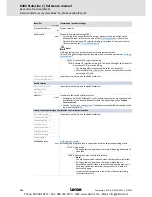
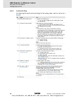
The following bit coded functional settings for the holding brake control can be made in
C02582
:
Bit
Option
Info
Bit 0 bMBrakeReleaseOut invert.
Activation of inverted control
• "1"
≡
Inverted logic of trigger signal for holding brake control
switching element
Bit 1 Horizontal brake protection
Brake response in case of pulse inhibit
• "1"
≡
In the case of a pulse inhibit, the actual speed value is
monitored which must reach the "Close" threshold value to cause
the holding brake to be applied.
Note:
• This function is only active if bit 3 (horizontal/winding
technology) is set as well. The function is used in order that, when
the controller is inhibited, the holding brake of a drive with
horizontal traverse path does not wear out during rotation.
• With vertical motion (bit 3 = 0), this function is not active.
Especially with hoists and activated pulse inhibit of the controller,
an immediate application of the brake is essential for safety-
related reasons!
Bit 2 with hoist inv. feedfwd. control
Direction of feedforward control with vertical/hoist technology:
• "0"
≡
Positive direction
• "1"
≡
Negative direction
Note:
Reversal (Ccw) is then considered.
Bit 3 Horizontal application
Direction of movement of the axis
• "0"
≡
The axis performs vertical movements. Gravitational
acceleration causes movements.
• "1"
≡
The direction of the axis is horizontal or rotary. The
gravitational acceleration does not cause any movement.
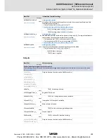
Bit 4 Feedforward control C2581
(from version 11.00.00)
Selection of the feedforward control value
• "0"
≡
Automatic selection.
–The torque saved at the last stop is used.
• "1"
≡
Manual selection.
–
bMBrakeStartValue2
= FALSE: The feedforward control value 1
set in
C02581/4
is used.
–
bMBrakeStartValue2
= TRUE: The feedforward control value set
in
C02581/5
is used.
Bit 5 Feedback monitoring
(from version 11.00.00)
Activation of status monitoring
• "1"
≡
The
bMBrakeApplied
input for status detection of the brake
(via a switching contact at the brake) is monitored after the
waiting time set in
C02589/3
has expired.
Bit 6 Sync ramp L_NSet_1
(from version 11.00.00)
Selection of the ramp time for the synchronisation process to
setpoint speed after the brake opening time has elapsed
Revised behaviour from version 11.00.00:
• "1"
≡
The ramp time of the effective acceleration of the ramp
function generator (
L_NSet_1
) is used (Lenze setting).
• "0"
≡
As before, the ramp time set in
C02610/1
is used.
Note:
The changeover can be dynamically both via the ramp parameter
and via bit 6.
Bit 7 Reserved
Phone: 800.894.0412 - Fax: 888.723.4773 - Web: www.clrwtr.com - Email: [email protected]

