Lake Shore Model 321 Autotuning Temperature Controller User’s Manual
D-4
Application Notes
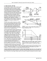
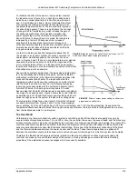
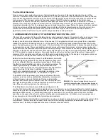
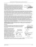
Since the thermal conductivity of cryogenic materials is finite, good practice dictates that the controller power output be
the same order of magnitude as the cooling power. If, for example, the cooling power is 0.2 watt, and 50 watts is
available, a change in set point to a higher temperature outside the proportional band of the controller will dump 50 watts
into the system block. Due to the thermal lag of the block, etc., a large temperature overshoot may occur, with the system
stabilizing only after several oscillations. This thermal lag can easily be observed since the sensor temperature will
continue to rise long after the output from the controller has been reduced to zero. The obvious way to reduce this effect is
to limit the heater power to the system to, for example, 0.5 watts. This can readily be done with a controller such as the
DRC-82C which has multiple maximum output power settings. The overshoot will therefore be smaller when the set point
is changed and the system will stabilize much faster although the rate of temperature rise will be less. Because changing
the power output setting affects the loop gain (dP/dT), it may be necessary to readjust the deviation amplifier gain
(controller gain setting) for optimum control. It is normally good practice to determine the power requirements for one's
system prior to or during the first experimental run. Some system manufacturers may have that information available and
may possibly supply a power load curve with the system.
Two other aspects of temperature control should be mentioned. First, ON-Off controllers are frequently encountered at
room temperature and above. As the name implies, such systems have only two states: power on when the temperature
is below the set point, and off when it is above. The proportional controller with excessive loop gain approximates this
mode. Although ON-OFF controllers perform adequately with large furnaces, for example, they are generally
unsatisfactory for cryogenic applications, because of the relatively short thermal time constants encountered at low
temperatures.
Secondly, some controllers, such as the DRC-82C, have a manually adjustable power output control. This control can be
used in either of two modes: (1) open loop, with a manual adjust of heater power
in place of
the signal from the deviation
amplifier and (2) automatic, where the adjustment is
in addition to
the controller's closed loop signal. Mode 1 is extremely
helpful in set up procedures and in subsequently determining the power levels associated with the desired temperatures.
In Mode 2, one can reduce and sometimes eliminate temperature offset by providing the required power without the need
for a large error signal to drive the output stage. This latter method has a name—manual reset—and serves as an
introduction to the next section on reset control.
IV PROPORTIONAL (GAIN) PLUS INTEGRAL (RESET) TEMPERATURE CONTROL
The manual reset adjustment described above varies markedly with the temperature set point and with the often changing
heater power demands of the system. Thus, it is normally neither convenient nor desirable to have to resort to such a
means of eliminating temperature droop (offset). Instead, suppose a circuit could be added to the loop that would: (1)
sense that there is a steady state offset signal within the proportional band; (2) make a bit-by-bit addition to the power
output, proportional to the magnitude of the offset; and (3) continue the corrective action until the offset is reset to zero.
The practical realization of this circuit is an integrator inserted between the deviation amplifier and the power stage. The
origin of the interchangeable terms "integral" control and (automatic) "reset" is evident.
How does a proportional-plus-integral controller behave in a cryogenic system?
First, in the idealized case, let us again assume an infinite thermal conductivity, which results in zero thermal resistance
between the sensor and the heater. The reset integrator continues to integrate until the error signal reaches zero, which
stops the integral action, but keeps its output at the level corresponding to that needed by the power stage to overcome
the droop. This output is now the only drive to the power stage since the proportional error signal has been forced to zero.
No overshoot will occur since zero thermal resistance eliminates the thermal lag which is the cause of overshoot. The
zero thermal time constant also means that
any
amount of reset will eventually force the system to zero error.
Before we switch the discussion back to real systems, let us deal with the nomenclature and units involved in integral
control. Automatic reset action can be expressed in terms of a time constant (minutes) or its inverse, reset rate (repeats
per minute). The reset time constant is the time required—measured in minutes—for the reset circuit to integrate to full
output with an input signal which is
constant
and equal to the proportional band error signal. The amount of reset action
can also be measured in "repeats per minute", or the number of times which the integrator can integrate between zero
and full output in a time period of one minute for the constant proportional band error signal. Thus, if the time constant
were, say, two minutes, this is the same as saying that the reset circuitry repeats the proportional action in two minutes, or
½ repeats per minute.
The term "reset windup" refers to a condition occurring in reset controller when an offset persists for a sufficiently long
time. The integration of the error, with time, will cause the integrator to saturate or "windup" at maximum output and
remain so until the control point is traversed. By the time this has happened, a large overshoot may have occurred. This
problem can be prevented by disabling the reset action when controller response goes outside the proportional band. A
controller such as the DRC-82C accomplishes this with an anti-reset windup (or reset inhibit) circuit.


