Lake Shore Model 321 Autotuning Temperature Controller User’s Manual
Service
6-1
CHAPTER 6
SERVICE AND CALIBRATION
6.0 GENERAL
This chapter describes the service and calibration for the Model 321 Temperature Controller.
Paragraph 6.1 provides general maintenance information. Changing power settings and fuse rating is
described in Paragraph 6.2. Rear panel connector definitions are provided in Paragraph 6.3. Optional
serial interface cable and adapters are described in Paragraph 6.4. The operating software EPROM
replacement procedure is provided in Paragraph 6.5. Power up errors are described in Paragraph 6.6.
Changing sensor input type is described in Paragraph 6.7. Paragraphs 6.8 thru 6.10 describe the
calibration procedure for the Model 321-01, -02, and -04, respectively. Two calibrations for each model
are provided: the first with the available precision equipment, the second without.
6.1 GENERAL
MAINTENANCE
If the keyboard locks up, press the Escape key for
≈
10 seconds. This will reset internal RAM to factory
default values. The instrument would then require the various user setpoints be reentered.
If there is no power, ensure you are plugged into a live outlet and that both ends of the power cord are
plugged in. Next check the fuse. Remove line cord then place a small slotted screwdriver in the slot of
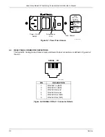
the small door at the rear of the unit to gain access to the fuse. See Figure 6-1. For 100/120 V
operation, the fuse rating is 1.5 A and the fuse type is 3AG Slow Blow. For 220/240 V operation, the
fuse rating is 0.75 A and the fuse type is 5×20 mm T. Test fuse with ohmmeter. Do not rely on visual
inspection of fuse.
To clean the Model 321 periodically to remove dust, grease and other contaminants, perform the
following:
1. Clean front/back panels and case with soft cloth dampened with mild detergent and water solution.
NOTE:
Do not use aromatic hydrocarbons or chlorinated solvents to clean the Model 321.
They may react with the silk screen printing on the back panel.
2. Clean surface of printed circuit boards (PCBs) using clean, dry air at low pressure.
6.2 CHANGING POWER SETTING AND FUSE RATING
There are two basic power configurations: domestic and foreign. Domestic has a single fuse on the hot.
Foreign has a double fuse arrangement for the hot and neutral. Units with specific power requirements
specified when purchased will be preconfigured at the factory for the proper power setting. If power
settings are incorrect for your application, use the following procedure to change the power settings.
WARNING:
To avoid potentially lethal shocks, turn off the instrument and disconnect it
from the AC power line before performing this procedure. Only qualified
personnel should perform this procedure.
1. Turn off unit.
2. Unplug line cord from rear of unit.
3. Use small screwdriver to open fuse drawer.
4. Pull out the fuse holder, rotate until the proper voltage setting is displayed through the window in
the fuse drawer. Place fuse holder back in fuse drawer.
5. Remove existing fuse(s). Replace with proper fuse ratings as follows: 1.5 A for 100/120 VAC;
or 0.75 A for 220/240 VAC.
6. Slide fuse drawer back into unit.
7. Plug line cord into rear of unit.
8. Perform initial setup and system checkout procedure in Paragraph 2.12.


