Lake Shore Model 321 Autotuning Temperature Controller User’s Manual
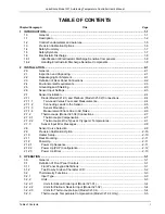
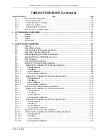
Table of Contents
v
LIST OF ILLUSTRATIONS
Figure No.
Title
Page
1-1
Model 321 Temperature Controller Front Panel ........................................................................... 1-2
1-2
Model 321 Block Diagram............................................................................................................. 1-6
2-1 Typical
Model 321 Rear Panel...................................................................................................... 2-2
3-1 Model
321
Front Panel ................................................................................................................. 3-1
3-2 Definition
of
2 by 16 Display ......................................................................................................... 3-2
3-3
Sensor Calibrations and Precision Options ................................................................................ 3-11
3-4 Record
of Zone Settings ............................................................................................................. 3-19
4-1
Optional Serial Interface Connections .......................................................................................... 4-1
5-1 Model
2001
RJ-11 Cable Assembly ............................................................................................. 5-3
5-2 Model
2002
RJ-11
to DB-25 Adapter............................................................................................ 5-3
5-3 Model
2003
RJ-11
to DE-9 Adapter.............................................................................................. 5-3
5-4 Model
3022
Rack Mount Kit.......................................................................................................... 5-4
5-5 Model
3026
Dual
Rack-Mount Shelf............................................................................................. 5-5
6-1 Power
Fuse Access ...................................................................................................................... 6-2
6-2 SERIAL
I/O
RJ-11
Connector Details........................................................................................... 6-2
6-3
ANALOG OUTPUT Connector Details ......................................................................................... 6-3
6-4
Diode and Platinum SENSOR Connector Details ........................................................................ 6-3
6-5 HEATER
Connector Details.......................................................................................................... 6-3
6-6
Model 2001 RJ-11 Cable Assembly Wiring Details ...................................................................... 6-4
6-7
Model 2002 RJ-11 to DB-25 Adapter Wiring Details .................................................................... 6-4
6-8
Model 2003 RJ-11 to DE-9 Adapter Wiring Details ...................................................................... 6-4
6-9
Location of Operating Software EPROMs .................................................................................... 6-5
6-10 Typical
Model 321 PCB Layout .................................................................................................... 6-9
B-1 Typical
Cryogenic Storage Dewar ................................................................................................B-1
LIST OF TABLES
Table No.
Title
Page
1-1
Instrument Electronic Information for Various Sensors and Temperature Ranges...................... 1-3
1-2
Model 321 Specifications.............................................................................................................. 1-4
2-1
Diode or Platinum Input Connections ........................................................................................... 2-4
2-2 Sensor
Curves .............................................................................................................................. 2-9
3-1 Sensor
Curves .............................................................................................................................. 3-6
4-1 Serial
Interface Specifications ...................................................................................................... 4-2
4-2
Serial Interface Program Control Properties................................................................................. 4-5
4-3 Visual
Basic
Serial Interface Program .......................................................................................... 4-6
4-4 Quick
Basic
Serial Interface Program........................................................................................... 4-7
4-5 Serial
Interface Command Summary............................................................................................ 4-9
B-1
Comparison of Liquid Helium to Liquid Nitrogen ..........................................................................B-1
C-1
Standard Diode and Platinum Curves ..........................................................................................C-1
C-2
Thermocouple Curves – Chromel Versus Gold/Iron.....................................................................C-2
C-3
Thermocouple Curves – Chromel Versus Copper........................................................................C-3

