


Lake Shore Model 321 Autotuning Temperature Controller User’s Manual
Installation
2-11
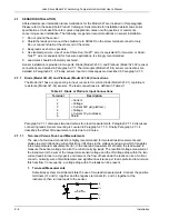
Within a cryostat, 30 gauge stranded copper lead wire (ND-30) is recommended for connection to the
heater. The heater leads should not run coincident with the sensor leads due to the possibility of
capacitive pick-up between the two sets of leads. If the heater leads must be close to the sensor leads,
wind (twist) them in such a manner that they cross at ninety degrees.
2.11 RACK MOUNTING
The Model 321 is shipped with plastic “feet” and is ready for use as a bench instrument. As an option,
the Model 321 can be installed in a standard 19 inch instrument rack. For information on the optional
Model 3022 Half-Rack Mounting Kit for a single controller, refer to Paragraph 5.3 and see Figure 5-4.
For information on the optional Model 3026 Dual Mounting Shelf for side-by-side mounting of two
controllers, refer to Paragraph 5.3 and see Figure 5-5.
2.12 POWER UP
The power up paragraph consists of a power up sequence in Paragraph 2.8.1. Power up (PUP)
Configuration is defined in Paragraph 2.8.2. Power up errors are explained in Paragraph 2.8.3.
2.12.1 Power Up Sequence
The following power up sequence occurs at power up.
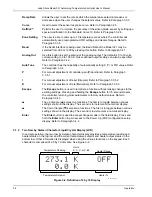
1. The first display gives the name of the unit.
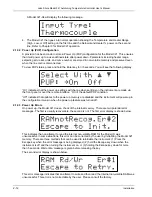
2. Next, the unit displays the current RS-232C Baud rate setting. The default setting is 300 Baud.
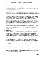
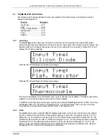
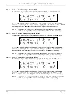
3. The temperature sensor input type is then displayed. The type of sensor depends on the model of
the instrument. A Model 321-01 will display the following message.
A Model 321-02 will display the following message.