Lake Shore Model 321 Autotuning Temperature Controller User’s Manual
Service
6-13
6.9.2 Optional Model 321-02 Calibration (Without Precision Resistor)
The optional Model 321-02 (Platinum Diode) calibration without precision resistor is presented in four
parts. First is list of test equipment in Paragraph 6.9.2.1. Second is the test setup in Paragraph
6.9.2.2. Third is the input calibration in Paragraph 6.9.2.3. Finally, analog output calibration is
provided in Paragraph 6.9.2.4. These procedures will be performed with power supplied to the unit.
Due to the presence of lethal currents, only personnel experienced in working with live circuits should
perform this procedure.
6.9.2.1 Test
Equipment
This procedure requires the following test equipment:
•
Digital Multimeter (DMM) with a 4½-digit display, capable of 4-lead resistive measurements.
• Resistor,
100
Ω
, as temperature stable as possible (20
–
50 ppm/°C), metal film preferred.
6.9.2.2 Test
Setup
Calibration test setup is as follows:
WARNING:
Lethal line voltage is present inside the box. Only qualified personnel
should attempt to perform this procedure.
1. Set power switch to off and disconnect power cord from rear of unit.
2. Use 5/64 hex key to remove four screws attaching top panel to unit.
3. Use 5/64 hex key to loosen two screws attaching bottom panel to unit.
4. Carefully remove back bezel.
5. Slide top panel back and remove from unit.
6.9.2.3 Input
Calibration
Use the following procedure to perform the input calibration.
1. Measure the resistance of the 100
Ω
resistor to the nearest 0.01
Ω
and write it down.
2. Place a short across the 100
Ω
resistor and attach to sensor input.
3 (+I)
4 (+V)
2 (V)
1 (I)
R
TEST
100
9
9
3. Power on (
l
) instrument.
4. Allow instrument to warm up for at least one hour.
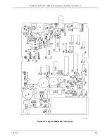
5. With DMM in DC voltage mode, attach test leads between TP2 (–) and TP1 (+).
6. Adjust R29 until DMM voltage reads 2.5000 ±0.0005 VDC.
7. Attach test leads to TP8 (GND1) and TP9 (Vref adj.).
8. Adjust R52 until DMM voltage reads 2.5000 ±0.0001 VDC.
9. Place positive test lead on TP7 (V+Buff).
10. Adjust R27 until DMM voltage reads 0.0000 ±0.0001 VDC.
11. Remove the short from the 100
Ω
resistor.
12. Configure the Model 321 to display units in ohms.
13. Adjust R42 until the display reads the value of the 100
Ω
resistor measured in Step 1. For
example, if the resistance measured 100.28
Ω
, R42 should be adjusted until the Model 321
displays 100.28
Ω
.


