Lake Shore Model 321 Autotuning Temperature Controller User’s Manual
6-16
Service
6.10.1.6 Internal Thermocouple Compensation Calibration
When a new or different thermocouple is attached to the instrument, and internal thermocouple
compensation is being used, it may be necessary to adjust the offset to compensate for
discrepancies in thermocouple material, leads and connections. Use the following procedure to
perform the internal thermocouple compensation calibration.
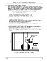
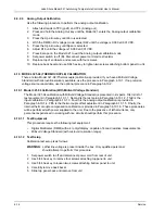
1. Open the Model 321 enclosure. Refer to Paragraph 6.10.1.2, Steps 1 – 5.
2. Short across the input with as short as lead as possible.
3. Configure the Model 321 to display units in °C.
4. Turn on thermocouple compensation.
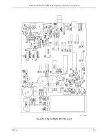
5. Adjust R60 until display reads room temperature (25 °C nominal).
6. Close the Model 321 enclosure. Refer to Paragraph 6.10.1.4, Steps 8 – 10.
6.10.2 Optional Model 321-04 Calibration (Without Millivolt Voltage Standard)
The optional Model 321-04 (Thermocouple) calibration without a millivolt voltage standard is
presented in six parts. First is list of test equipment in Paragraph 6.10.2.1. Second is the test setup in
Paragraph 6.10.2.2. Third is the input calibration in Paragraph 6.10.2.3. Fourth is the analog output
calibration is provided in Paragraph 6.10.2.4. Fifth is the thermocouple offset adjustment in Paragraph
6.10.2.5. Finally, the internal thermocouple compensation calibration is provided in Paragraph
6.10.2.6. These procedures will be performed with power supplied to the unit. Due to the presence of
lethal currents, only personnel experienced in working with live circuits should perform this procedure.
6.10.2.1 Test
Equipment
This procedure requires the following test equipment
•
Digital Multimeter (DMM) with a 4½-digit display, capable of 4-lead resistive measurements.
•
Voltage source capable of providing a stable, nominal ±44.0 mV DC.
6.10.2.2 Test
Setup
Calibration test setup is as follows:
WARNING:
Lethal line voltage is present inside the box. Only qualified personnel
should attempt to perform this procedure.
1. Set power switch to off and disconnect power cord from rear of unit.
2. Use 5/64 hex key to remove four screws attaching top panel to unit.
3. Use 5/64 hex key to loosen two screws attaching bottom panel to unit.
4. Carefully remove back bezel.
5. Slide top panel back and remove from unit.

