


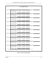


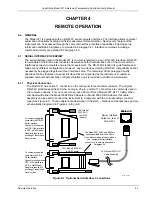


Lake Shore Model 321 Autotuning Temperature Controller User’s Manual
3-22
Operation
3.4.4 Power Up (PUP) Configuration
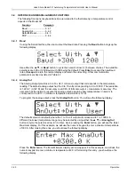
A provision has been made to store a Power Up (PUP) configuration for the Model 321. This ensures
that it will power up to a user-defined state after power down. Parameters including heater range,
setpoint, gain, reset, units, and curve number are stored in non-volatile memory and preserved even
when the line cord is disconnected.
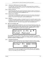
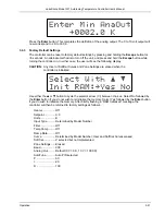
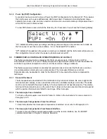
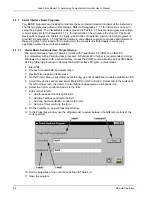
To view PUP status, press and hold the Enter key for
≈
5 seconds. You will see the following display.
“On” indicates that the power up settings will change when settings on the instrument are made via
the front panel or over the remote interface. “On” is the default PUP condition.
“Off” indicates that updates to the power up memory are disabled and the instrument will power up in
the configuration it was in when the power up feature was turned off.
3.5 THERMOCOUPLE CONTROLLER OPERATION (MODEL 321-04 ONLY)
The thermocouple input option is designed for thermocouple sensors. Chromel-AuFe (0.07%),
Chromel-AuFe (0.03%), E, K, and T thermocouples are supported with internal curves that enable the
controller to operate in temperature units (°C and K) as well as voltage in millivolts.
The thermocouple input utilizes a secondary temperature sensor to monitor the Reference Junction
(room) temperature and provide curve compensation. Thermocouple (Reference Junction)
Compensation can be disabled in order for the Model 321 to be used with external compensation
techniques.
3.5.1 Sensor
Attachment
Thermocouple leads are attached to the terminal block by aluminum screws. Be sure to tighten the
terminal screws carefully. Loose connections will result in unstable readings and control. The leads
must be connected with the proper polarity or the input option will not operate properly. The positive
terminal of the terminal block is on the side of the V+ label on the back panel and should correspond
with the positive thermoelement listed for each type of thermocouple.
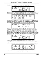
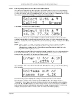
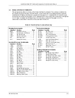
3.5.2 Thermocouple Curve Selection
To choose a thermocouple curve listed in Table 2-3. Refer to the instructions for curve selection in
Paragraph 3.2.5.
3.5.3 Thermocouple Compensation From Front Panel
To determine whether thermocouple compensation is selected or not, refer to Paragraph 3.2.3.
3.5.4 Thermocouple Compensation From Remote Interface
To select or prevent thermocouple compensation over the remote interface, use the ACOMP
command described in Chapter 4 - Remote Operation.