Lake Shore Model 321 Autotuning Temperature Controller User’s Manual
Service
6-17
6.10.2.3 Input
Calibration
Use the following procedure to perform the input calibration.
1. Power on (
l
) instrument.
2. Allow instrument to warm up for at least one hour.
3. Short across the input with as short a lead as possible.
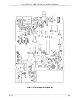
4. Attach test leads to TP8 (gnd1) and TP9 (Vref adj.).
5. Adjust R52 until DMM voltage reads 2.5000 ±0.0001 VDC.
6. Configure the Model 321 to display units in millivolts.
7. Turn off temperature compensation.
8. Adjust R27 until the Model 321 display reads exactly 0.0000 mV DC.
9. Remove short from input and attach voltage source.
4 (+V)
2 (V)
++
Voltage
Standard
10. Adjust voltage source to a n44.0 mV DC.
11. Attach the DMM to the input. DMM should be in the DC millivolt mode.
12. Adjust R43 until Model 321 display exactly matches the DMM reading.
13. Reverse voltage source to -44.0 mV DC. The Model 321 display should match the DMM
reading within ±0.002 mV DC. If not, set voltage source to zero volts and repeat steps 8
through 13.
6.10.2.4 Analog Output Calibration
Use the following procedure to perform the analog output calibration.
1. Attach test leads to TP3 (GND1) and TP4 (Analog out).
2. Press and hold the Analog Out key until the Model 321 enters the Analog output calibration
mode.
3. Press the Up arrow key until Zero is selected.
4. With the DMM in DC voltage mode, adjust R22 until the voltage is 0.000 ±0.001 VDC.
5. Press the Up arrow key until Span is selected.
6. Adjust R18 until the voltage is 10.000 ±0.001 VDC.
7. Press Escape on the Model 321 to exit the Analog output calibration mode.
8. Set power switch to off (
O
). Disconnect power cord and test resistor.
9. Replace top of enclosure and secure with four screws.
10. Replace back bezel and use 5/64 hex key to tighten two screws attaching bottom panel to unit.


