N700 Operating Instructions and Parts Manual
11. Explanation of C-Group
126
(5) When torque control signal is selected in intelligent output selection, torque limit above-
mentioned turns ON while torque limit function is performed.
(6) Torque limit when 00 (4 quadrant mode) is chosen by torque limit choice (C006) becomes the
bottom figure.
Torque T
+
+
-
-
Reverse
regenerating
C008
→
Forward
motoring
C007
→
Reverse
C009
→
motoring
Forward
Regenerating
C010
→
Fig. 11- 2 Torque limit (4 quadrant mode)
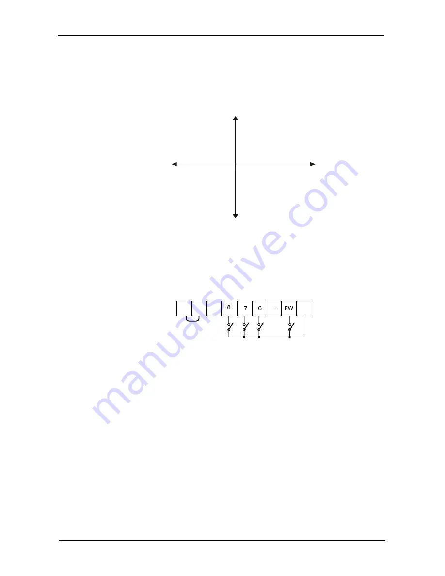
(7) When 01 (terminal switching) is chosen by torque limit choice (C006), torque limit 1 changed
by torque limit switching 1,2 assigned to intelligent input terminal 1~4 are set up as the bottom
figure.
(Example) When torque limit switching 2 (31) was assigned to torque limit switching 1 (30),
an intelligent input terminal 8 in intelligent input terminal 7.
CM1
TL
(29)
FWD
(0)
TRQ1
(30)
CM1
P24 PLC
TRQ2
(31)
Fig. 11- 3 Torque limit setting in intelligent input terminal
(8) When using torque limit function at low speed level, use overload restriction together.
11.4
External braking control function (C012 ~ C018)
(1) This is a function that the inverter controls external braking used in systems like elevators. By
braking control function selection(C012) is set to valid(01), this function is performed as the
following below.
①
When running command turns on, the inverter begins to operate and accelerate to
releasing frequency.
②
After output frequency arrives at the releasing frequency, the inverter output breaking
releasing signal (BRK) after waiting for confirmation of releasing braking which is set in
(C013). However, if output current of the inverter is within releasing current which is set in
(C018), the braking releasing signal would not output. In this case, the inverter will incur a
trip signal and output the braking error signal (BER).
③
When braking confirmation signal (BOK) is set to intelligent input terminals, if braking


