79
Section V.
Parameter Function Table
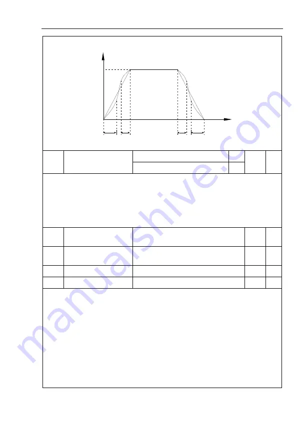
which the changing slope of output frequency change to zero. The changing slope of output frequency is
fixing within the time of t1 and t2.
Fig.5-11S-curve acceleration/deceleration schematicdiagram A
P6.10
Stop mode
Speed-Down to stop
0
0
☆
Free stop
1
0
:
Deceleration to stop
When the stop command is valid, the inverter will decelerate to stop according to the setup
deceleration time.
1
:
Free stop
When the stop command is valid, the inverter will terminate the output immediately and the load will
coast to stop according to the mechanical inertia.
P6.11
DC braking initial frequency
at stop
0.00Hz~maximum frequency
0.00Hz
☆
P6.12
DC braking waiting time at
stop
0.0s~36.0s
0.0s
☆
P6.13
DC braking current at stop
0%~100%
0%
☆
P6.14
DC braking time at stop
0.0s~100.0s
0.0s
☆
DC brake initial frequency at stop
:
During the process of decelerating to stop, when the running
frequency at stop reaches this frequency, it will start the process of DC brake.
DC brake waiting time at stop
:
Prior to the beginning of DC brake at stop, the inverter will terminate
the output, and then start DC brake after this delay time. It is used to prevent over current fault due to DC
brake which starts at the time of higher velocity.
DC brake current at stop
:
The DC brake quantity added shall be set according to the percentage
setting of the rated current of the inverter. The higher the brake current is, more powerful the brake effect is.
DC brake time at stop
:
It refers to the continuous DC brake time. If this DC brake time is set to 0, it
indicates that there is no DC brake process, and the inverter will stop according to the setting process of
decelerating to stop.
The process of DC brake at stop is as shown in Figure below.
t1
t2
t2
t1
t
Output frequency Hz
Setting frequency f
Содержание HV590 Series
Страница 1: ...HV590 Series Frequency Inverter User Manual HNC Electric Limited ...
Страница 189: ......
Страница 192: ......


