115
Section V.
Parameter Function Table
MIN(AI1,AI2)
6
MAX(AI1,AI2)
7
A0.03
Torque digital setup in torque
control mode
-200.0%~200.0%
150%
☆
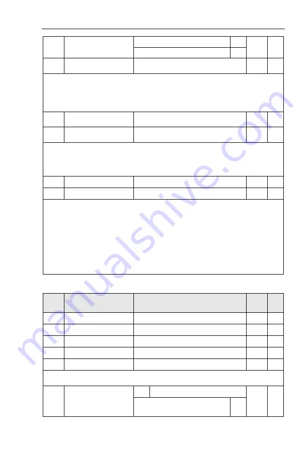
A0.01 is used to select torque set source. There are totally 8 kinds of torque set mode.
Torque set is a relative value, which 100% corresponding to inverter rated torque. Set range
:
200.0%~200.0%.Maximum torque is 2 times that of inverter rated torque
When the torque is set by selection 1~7, 100% of communication ,analog input , pulse input
corresponding to A0.03.
A0.05
Torque control forward
maximum frequency
0.00Hz~Maximum frequency(P0.10)
50.00Hz
☆
A0.06
Torque control reverse
maximum frequency
0.00Hz~Maximum frequency(P0.10)
50.00Hz
☆
A0.05, A0.06 are used to set forward or reverse maximum running frequency in torque control mode.
In inverter toque control mode, if load torque is less than motor output toque, the motor revolving
speed would speed up. In case of galloping or other accidents of mechanical system , motor maxi mum
revolving speed must be limited.
A0.07
Torque control acc. time
0.00s~65000s
0.00s
☆
A0.08
Torque control dec. time
0.00s~65000s
0.00s
☆
In torque control mode , rate of speed change of motor and load is decided by the difference
between motor output toque and load torque. Therefore, motor speed may change fast, causing noise
or excessive mechanical stress problems. By setting the torque control acc./dec. time, can make the
motor speed changes smoothly.
A0.07 and A0.08 should be set to 0.00s in situations where torque rapid response is needed.
E.g
:
Two motors drive the same load, to make sure of load uniform distribution , one is set as host
inverter(speed control mode) and another is the slave one(torque control mode). Actual output torque of
the host inverter is the torque command of the slave, and slave torque is required to quickly follow the
host torque, then torque control acc./dec. time is set to 0.00s for the slave inverter.
5.19
VirtualIO
:
A1.00-A1.21
Code
Description/
Keyboard Display
Setting Range
Factory
Setting
Change
Limit
A1.00 Virtual VDI1 function selection
0~59
0
★
A1.01 Virtual VDI2 function selection
0~59
0
★
A1.02 Virtual VDI3 function selection
0~59
0
★
A1.03 Virtual VDI4 function selection
0~59
0
★
A1.04 Virtual VDI5 function selection
0~59
0
★
Functions of virtual VDI1~VDI5 are equal to DI terminals on control board. VDI1~VDI5 can be used
as multi-function digital input terminals, for details please refer to description of P4.00 ~P4.09 .
A1.05
Virtual VD1 terminal valid
state set mode
1bit
Virtual VDI1
00000
★
State of virtual VYx decides whether
VDI is effective
0
Содержание HV590 Series
Страница 1: ...HV590 Series Frequency Inverter User Manual HNC Electric Limited ...
Страница 189: ......
Страница 192: ......


