100
Section V.
Parameter Function Table
frequency. In the load-off protection period, if the load restored, the inverter automatically restore to the set
running frequency.
P9.67
Over speed detection value
0.0%~50.0%(Maximum frequency)
20.0%
☆
P9.68
Over speed detection time
0.0s~60.0s
1.0s
☆
This function is only valid in speed sensor vector control.
Inverter fault alarm when motor actual revolving speed exceeds the set frequency(excess value
>
P9.67 ,duration time
>
P9.68) .Fault No. 43=Err43.
P9.69
Excessive speed deviation
detection value
0.0%~50.0%(Maximum frequency)
20.0%
☆
P9.70
Excessive speed deviation
detection time
0.0s~60.0s
5.0s
☆
This function is only valid in speed sensor vector control.
Inverter fault alarms when deviation detected between motor actual revolving speed and the set
frequency(deviation
>
P9.69, duration time
>
P9.70). Fault No. 42=Err42.
P9.70=0.0s
:
Excessive speed deviation fault detection is canceled.
5.12
PID function group
:
PA.00-PA.28
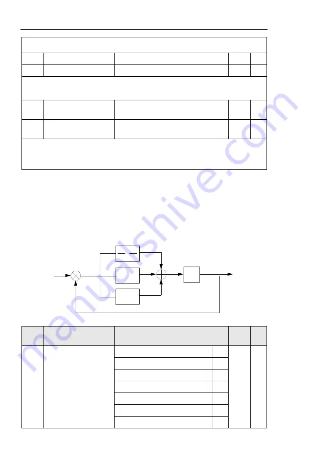
PID control is a common method used in process control. Through the proportional,
integration and differential calculation on the difference between feedback signal and target signal
of the controlled parameter, PID control adjusts the output frequency of the inverter and forms
negative feedback system, making the controlled parameter stabilized on the target parameter.
PID control is appliedto several process controls such as flow control, pressure control and
temperature control.The schematic diagram for control is as shown in Fig. 5-25.
Fig.5-25PID process schematic diagram
Code
Description/
Keyboard Display
Setting Range
Factory
Setting
Change
Limit
PA.00
PID reference source
PA.01 setup
0
0
☆
AI1
1
AI2
2
AI3(Potentiometer)
3
PULSE(DI5)
4
Communication
5
MS command
6
+
-
Target quantity
Feedback quantity
PID output control quantity
P
1
Td*s+1
1
Ti
1
S
Содержание HV590 Series
Страница 1: ...HV590 Series Frequency Inverter User Manual HNC Electric Limited ...
Страница 189: ......
Страница 192: ......


