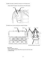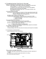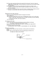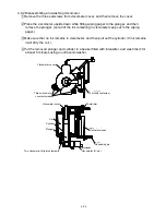
4-17
4.8 Pump parts replacement
4.8.1
Pump Unit Replacement Procedure
1
Perform “Ink drainage” to “Pressure relief”.
2 Turn off the power supply.
3
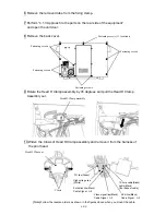
Perform “4.1.3 Access to the parts on the rear side of the equipment”.
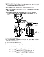
4 Remove the clamps (3 positions) that fix the wires.
5 Remove the connectors of the electric parts (7 positions) (motor, pressure sensor,
viscometer (3 positions), level sensor and float sensor)
5 positions
1 position
1 position
Содержание IJ RX2
Страница 1: ...Service Manual HITACHI Printer Model RX2 Revision Feb 2014 Version A ...
Страница 13: ...1 8 2 External views Rear side 1 2 2 Main body internal ...
Страница 14: ...1 9 1 2 3 Print head ...
Страница 101: ...3 26 Circuit diagram of EZJ127A ...
Страница 102: ...3 27 Circuit diagram of EZJ127B ...
Страница 116: ...3 41 Circuit diagram of EZJ129 ...
Страница 164: ...4 40 5 Reset the time of the R air filter to 0 on the Parts usage time management screen ...
Страница 247: ...7 Attached Drawing 7 1 Circulation System Diagram Circulation System Diagram 7 1 ...
Страница 248: ...7 2 Electrical Connection Diagram 7 2 1 Electrical Connection Diagram RX2 S Standard model 7 2 ...
Страница 249: ...7 3 7 2 2 Electrical Connection Diagram RX2 B Basic model 7 3 ...
Страница 252: ... Nozzle diameter 65μm 7 6 7 4 Dimensions around charge electrode and deflection electrode 循環系統図 ...


