5-14
2)
The efficient way to use the ultra-sonic cleaning machine
The efficient way to use the ultra-sonic cleaning machine for ultra-sonic cleaning of the nozzle orifice
1: How to find the optimum cleaning position
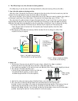
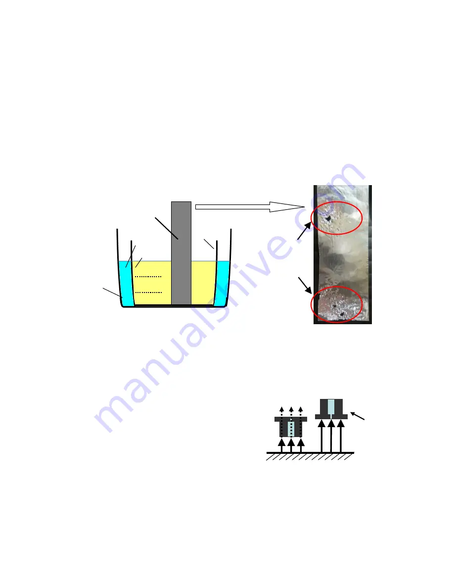
When the orifice is cleaned by the ultra-sonic cleaning machine, the aluminum foil can be used as a good trial
sample to find the right position to place the nozzle orifice in the machine.
As shown in the Figure 1 below, when the aluminum foil is put in the ultra-sonic cleaning machine then pulled out
and observed, spots where the surface status of the aluminum foil changes show up as in Photo 1. *1*2
The spots where the surface status is changed (the spots where the
“holes” are in Photo 1) are the location
(height) where the ultra-sonic cleaning is made most effectively. Therefore, to conduct the ultrasonic-cleaning
effectively, the height should be adjusted by using the jig as shown in the Photo 2, prior to ultra-sonic cleaning.
*1 the change of the aluminum foil surface may be influenced by the liquid level of the cleaning tank.
If NO change is made to the aluminum foil, lower/increase the liquid level then check the status
of the surface again.
*2 If the frequency of the ultra-sonic cleaning machine reaches 45 kHz, the change in surface of the
aluminum foil may not appear.
Figure 1. Example-Placing aluminum
foil in the ultra-sonic cleaning machine
Photo 1. Status of aluminum foil after
1
–minute ultra –sonic cleaning
2: Notice, etc.
1. The material of the inner tank should NOT be made of resin. Either SUS or Glass is preferred.
Its thickness shall be thin. (Because the sound wave is absorbed [reduced].)
2. The up-and-down oscillation in the inner tank may work effectively if the optimal location (height) is unknown.
3. The opening of the orifice shall face down.
(The sound wave is attenuated by orifice’s own thickness.
It is preferred that the position you wish to clean
be placed facing the bottom of the cleaning tank.)
4. Note that the ultra-sonic cleaning shows NO effect if there is air in the opening of the orifice.
5. The unevenness in cleaning strength exists in the horizontal direction in the cleaning tank.
Normally, it tends to be stronger in the center. By changing the horizontal position of the aluminum foil and
understanding the characteristics of the cleaning, the position to place the orifice can be optimized.
Because of the diffuse reflection, it is not always the case that the cavitations occurs only at the theoretical
positions. (By using the aluminum foil, the positions can be found anyway.)
Aluminum foil
Water
Cleaning
tank
Cleaner
Inner
tank
Cavitation is
working efficiently.
(Holes may be
created.)
○
△
Orifice opening
face down.
Содержание IJ RX2
Страница 1: ...Service Manual HITACHI Printer Model RX2 Revision Feb 2014 Version A ...
Страница 13: ...1 8 2 External views Rear side 1 2 2 Main body internal ...
Страница 14: ...1 9 1 2 3 Print head ...
Страница 101: ...3 26 Circuit diagram of EZJ127A ...
Страница 102: ...3 27 Circuit diagram of EZJ127B ...
Страница 116: ...3 41 Circuit diagram of EZJ129 ...
Страница 164: ...4 40 5 Reset the time of the R air filter to 0 on the Parts usage time management screen ...
Страница 247: ...7 Attached Drawing 7 1 Circulation System Diagram Circulation System Diagram 7 1 ...
Страница 248: ...7 2 Electrical Connection Diagram 7 2 1 Electrical Connection Diagram RX2 S Standard model 7 2 ...
Страница 249: ...7 3 7 2 2 Electrical Connection Diagram RX2 B Basic model 7 3 ...
Страница 252: ... Nozzle diameter 65μm 7 6 7 4 Dimensions around charge electrode and deflection electrode 循環系統図 ...

