4-25
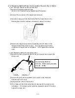
4.9.3 Viscometer assembly procedure
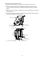
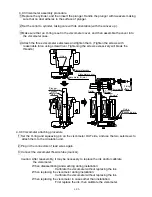
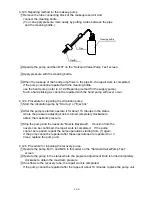
1 Replace the cylinder, and then insert the plunger. Handle the plunger with tweezers making
sure that no dust adheres to the surface of plunger.
2 Set the collar to cylinder, taking care with its orientation (with the convex up).
3 Make sure that an O-ring is set in the viscometer cover, and then assemble the cover into
the viscometer case.
4 Attach the three viscometer setscrews and tighten them. (Tighten the screws with
reasonable force using screwdriver. Tightening the screws excessively will break the
threads.)
4.9.4 Viscometer attaching procedure
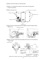
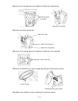
1 Set the O-ring and squeezing pin on the viscometer OUT side, and use the two setscrews to
attach them to the circulation unit.
2 Plug in the connectors of lead wires again.
3 Connect the viscometer IN-side tube (mark G).
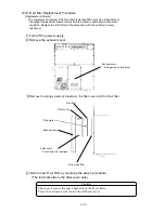
Caution: After reassembly, it may be necessary to replace the ink and/or calibrate
the viscometer.
When disassembling and washing during installation:
Calibrate the viscometer without replacing the ink.
When replacing the viscometer during installation:
Calibrate the viscometer without replacing the ink.
When replacing the viscometer in cases other than installation:
First replace the ink, then calibrate the viscometer.
O-ring
Viscometer case
Viscometer IN joint
Viscometer cover
Plunger
Cylinder
Coil
Collar
O-ring
O-ring
O-ring
Thermistor
Fixing
plate
Squeezing pin
Содержание IJ RX2
Страница 1: ...Service Manual HITACHI Printer Model RX2 Revision Feb 2014 Version A ...
Страница 13: ...1 8 2 External views Rear side 1 2 2 Main body internal ...
Страница 14: ...1 9 1 2 3 Print head ...
Страница 101: ...3 26 Circuit diagram of EZJ127A ...
Страница 102: ...3 27 Circuit diagram of EZJ127B ...
Страница 116: ...3 41 Circuit diagram of EZJ129 ...
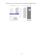
Страница 164: ...4 40 5 Reset the time of the R air filter to 0 on the Parts usage time management screen ...
Страница 247: ...7 Attached Drawing 7 1 Circulation System Diagram Circulation System Diagram 7 1 ...
Страница 248: ...7 2 Electrical Connection Diagram 7 2 1 Electrical Connection Diagram RX2 S Standard model 7 2 ...
Страница 249: ...7 3 7 2 2 Electrical Connection Diagram RX2 B Basic model 7 3 ...
Страница 252: ... Nozzle diameter 65μm 7 6 7 4 Dimensions around charge electrode and deflection electrode 循環系統図 ...


