4-28
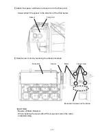
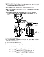
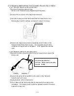
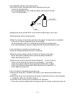
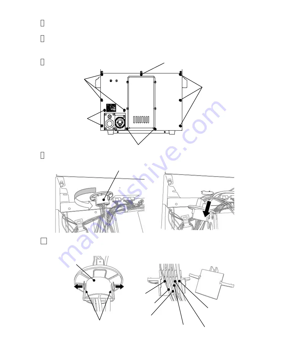
6 Remove the removed tube from the fixing clamp.
7
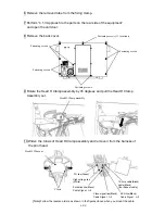
Perform “4.1.3 Approach to the parts on the rear side of the equipment”
and open the unit door.
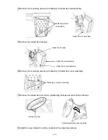
8 Remove the back cover.
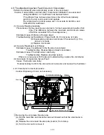
9 Rotate the Head H Clamp assembly by 45 degrees and pull the Head H Clamp
Assembly out.
10 Widen the Claws of Head H Clamp assembly and remove it from the harness of
the print head.
Fastening screws (11 locations)
Fastening screws
Fastening screws
Fastening screws
screws
Fastening screws
Head H Clamp assembly
assembly
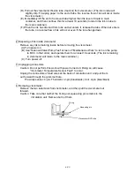
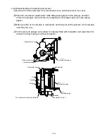
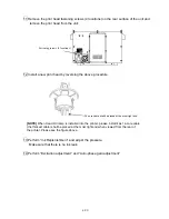
[Note] Follow the reverse orders as shown in the figures above when you mount the cable.
Head H Clamp assembly
assembly
High voltage line
(White)
Video signal line(Black)
Cable Signal
: №
3
Excitation line(Black)
Cable Signal
: №
5
14-core cable(Black)
cable(Black)
[the thickest cable]
APH line(Black)
Cable Signal
: №
2
Claws
FG line(Green)
Содержание IJ RX2
Страница 1: ...Service Manual HITACHI Printer Model RX2 Revision Feb 2014 Version A ...
Страница 13: ...1 8 2 External views Rear side 1 2 2 Main body internal ...
Страница 14: ...1 9 1 2 3 Print head ...
Страница 101: ...3 26 Circuit diagram of EZJ127A ...
Страница 102: ...3 27 Circuit diagram of EZJ127B ...
Страница 116: ...3 41 Circuit diagram of EZJ129 ...
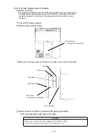
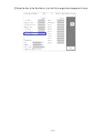
Страница 164: ...4 40 5 Reset the time of the R air filter to 0 on the Parts usage time management screen ...
Страница 247: ...7 Attached Drawing 7 1 Circulation System Diagram Circulation System Diagram 7 1 ...
Страница 248: ...7 2 Electrical Connection Diagram 7 2 1 Electrical Connection Diagram RX2 S Standard model 7 2 ...
Страница 249: ...7 3 7 2 2 Electrical Connection Diagram RX2 B Basic model 7 3 ...
Страница 252: ... Nozzle diameter 65μm 7 6 7 4 Dimensions around charge electrode and deflection electrode 循環系統図 ...


