5-8
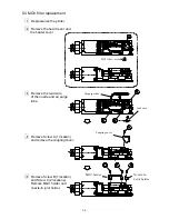
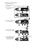
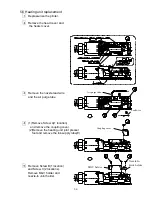
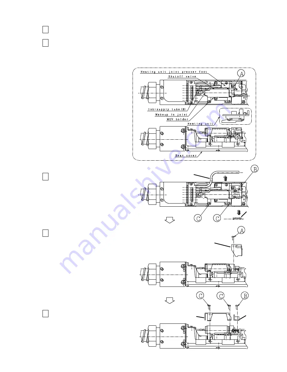
5.6 Heating unit replacement
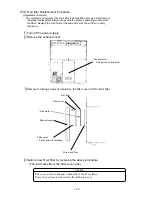
1
Depressurize the printer.
2
Remove the head cover and
the heater cover.
3
Remove the nozzle lead wire
and the air purge tube.
4
(1)Remove Screw A(1 location)
and remove the coupling cover.
(2)Remove the heating unit joint presser
foot and remove the ink-supply tube(E)
5
Remove Screw B(1 location)
and Screw C(2 locations).
Remove MGV holder and
nozzle-In Joint holder.
Air purge tube
Lead wire
MGV holder
Coupling cover
Nozzle-In
Joint holder
3 P ツ ギテオサエ
Содержание IJ RX2
Страница 1: ...Service Manual HITACHI Printer Model RX2 Revision Feb 2014 Version A ...
Страница 13: ...1 8 2 External views Rear side 1 2 2 Main body internal ...
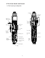
Страница 14: ...1 9 1 2 3 Print head ...
Страница 101: ...3 26 Circuit diagram of EZJ127A ...
Страница 102: ...3 27 Circuit diagram of EZJ127B ...
Страница 116: ...3 41 Circuit diagram of EZJ129 ...
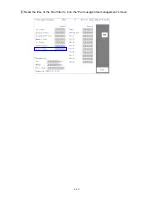
Страница 164: ...4 40 5 Reset the time of the R air filter to 0 on the Parts usage time management screen ...
Страница 247: ...7 Attached Drawing 7 1 Circulation System Diagram Circulation System Diagram 7 1 ...
Страница 248: ...7 2 Electrical Connection Diagram 7 2 1 Electrical Connection Diagram RX2 S Standard model 7 2 ...
Страница 249: ...7 3 7 2 2 Electrical Connection Diagram RX2 B Basic model 7 3 ...
Страница 252: ... Nozzle diameter 65μm 7 6 7 4 Dimensions around charge electrode and deflection electrode 循環系統図 ...

