background image

2-18 


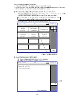
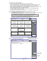
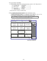
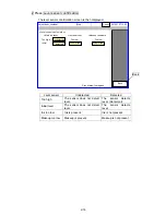
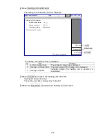
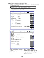
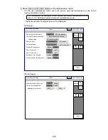
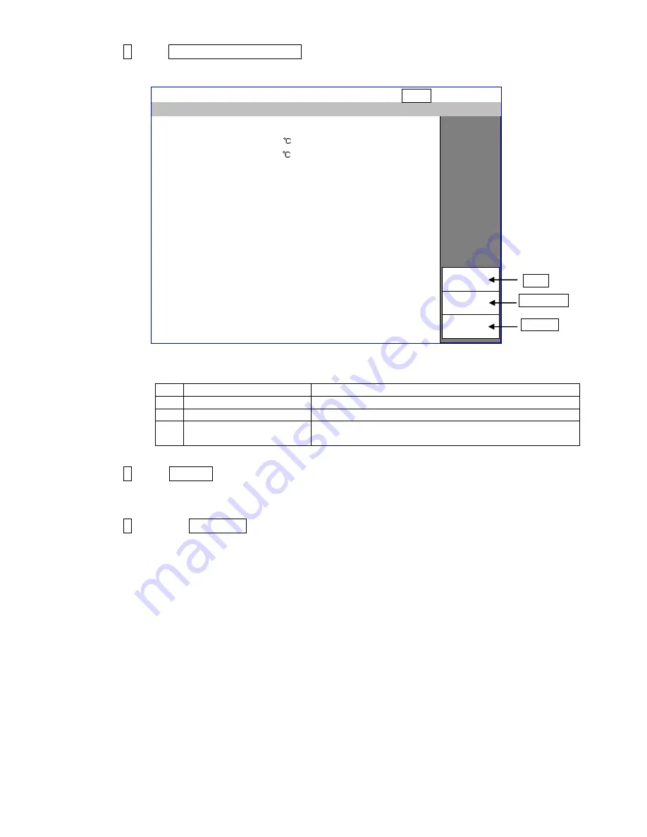
  2 Press Heating unit confirmation .


The Heating unit confirmation screen is displayed. 


  The heating unit operation state is displayed. 

№ 

Item 

Contents 

Ambient temperature 

The ambient temperature is displayed. 

Heating unit temperature 

The temperature of the heating unit is displayed. 

Heating unit status 

Indicates  whether  the  heating  unit  is  activated  or 
deactivated. 


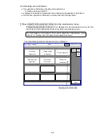
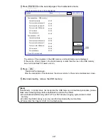
  3 When Activate is pressed, the heating unit turns ON. 


Heating unit temperature rises. 


The heating unit state is displayed as “Activated”. 

 
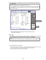
  4 When the Deactivate is pressed, the heating unit turns OFF. 


Activate 

Adjust./oper. checkout 

<Heating unit confirmation> 

Ambient temperature :      10 (    ) 

Deactivate 

Abort 

Proc. status: In progress 

Heating unit temp.      :   


20 (    ) 

Heating unit status      : Deactivated 

Execution takes 5 minutes. 

[Stop                    ] 

2015.07.07 12:45 

Com=0 

Activate 

Deactivate 

Abort 

Содержание IJ RX2

Страница 1: ...Service Manual HITACHI Printer Model RX2 Revision Feb 2014 Version A ...

Страница 2: ...ata 2 51 2 21 Addition of 2 21 Rescue soft 2 57 4 14 Addition of 4 14 R air filter Replacement Procedure 4 38 4 15 Addition of 4 15 Liquid Spill Check on Exhaust Duct 4 41 5 9 Addition of 5 9 Nozzle Orifice Cleaning 5 13 6 2 26 Addition of 6 2 26 Charge Voltage Too Low 6 24 6 5 20 Addition of 6 5 20 Startup process after long term shutdown and How to restore the operation 6 65 6 5 21 Addition of 6...

Страница 3: ... gain adjustment 2 13 2 3 5 Level sensor confirmation 2 15 2 3 6 Heating unit confirmation 2 17 2 4 Test of solenoid valve pump 2 19 2 5 Download 2 20 2 6 Calibration of viscometer 2 22 2 6 1 Calibration of viscometer 2 22 2 6 2 Operation test of viscometer 2 23 2 7 Ink concentration control 2 24 2 8 System reset 2 25 2 9 Back up 2 26 2 10 Unit information 2 27 2 11 Handling of the warning Product...

Страница 4: ...127 board I O board 3 20 3 3 8 EZJ132 board Ink circulation module connection board 3 28 3 3 9 EZJ113 board Power relay board 3 28 3 3 10 EZJ114 board LED SW board 3 30 3 3 11 EZJ119A board Relay output board Optional board 3 30 3 3 12 EZJ130 board Software option control board 3 32 3 3 13 EZJ129 board Software option terminal board 3 34 3 3 14 Multiple Power Supply 3 42 3 3 15 High voltage power ...

Страница 5: ...nfiguration 5 1 5 2 Cable running direction 5 2 5 3 Gutter configuration and replacement method 5 3 5 3 1 Gutter configuration 5 3 5 3 2 Replacement method 5 3 5 4 MGV filter replacement 5 4 5 5 Shutoff valve MV9 replacement 5 6 5 6 Heating unit replacement 5 8 5 7 APH board replacement 5 10 5 8 Nozzle replacement 5 11 5 9 Nozzle Orifice Cleaning 5 13 6 Troubleshooting 6 1 6 1 Troubleshooting List...

Страница 6: ...ing on the situation After the manual has been read it must be stored in such a location that all printer operation personnel can refer to it at all times All the instructions set forth in this manual are important and must therefore be observed without fail Pictograph Examples The symbols are used to indicate precautions including those related to potential warnings to be observed Detailed inform...

Страница 7: ...t tweezers a screwdriver or any other metal article into the ink ejection hole in the end of the print head When the printer is ready to print a high voltage approximately 6 kV is applied to the deflection electrode section in the print head Exercise caution to avoid electric shock injury and fire Be sure to shut off the power before replacing electrical components power PC board etc Be sure to un...

Страница 8: ... mouth or soil your hands or clothing If any ink or makeup enters your eyes or mouth immediately flush with warm or cold water and consult a physician Before servicing the printer be sure to stop the ink ejection Because ink or makeup may splash into your eyes or mouth or onto your hands or clothing If any ink or makeup enters your eyes or mouth immediately flush with warm or cold water and consul...

Страница 9: ...leak of ink or makeup inside the printer while the printer is running or being maintained wipe it off promptly with wiping paper or something similar Then with the maintenance cover open stop the printer power it down and repair the leak Continuing operation with a leak of ink or makeup will cause an anomaly resulting in abnormal printing Ink and makeup are flammable They may therefore catch on or...

Страница 10: ...akeup could spurt out when the outside cover is removed Therefore when unplugging do not hold the bottle near your face place the can on a level surface open while covering the opening with a rag etc Ink and makeup must be stored as flammable liquids Storage must comply with local regulatory requirements Consult the appropriate regulatory agency for further information Ink and makeup must be handl...

Страница 11: ...ion screen When manipulating the Touch panel use only fingers If the touch panel is operated with metal and or sharp objects such as ball point pen it may malfunction or break down When replaced with an incorrect type of battery the battery is in danger of exploding Be sure to replace the battery with the one specified by parts list When disposing of the battery lithium battery you must comply wit...

Страница 12: ...1 7 1 2 Structure of each part in the main body 1 2 1 External views 1 External views RX2 S 2 External views RX2 B ...

Страница 13: ...1 8 2 External views Rear side 1 2 2 Main body internal ...

Страница 14: ...1 9 1 2 3 Print head ...

Страница 15: ...ition to those given above Standard UL CUL certified Rating 125 V 7A or more Plug NEMA5 15P Cable Type SJT 18AWG 60 C or higher Cable length 1 5 4 5 m Use the proper plug Be sure to ground properly Locate the equipment near an electrical outlet and arrange so it can be easily disconnected Use a power cable that is within the specified range Do not bundle the light electrical cable together with th...

Страница 16: ...the electrical outlet before performing work Be careful not to get shocked when checking with the cover open Precautions concerning electrical shock Inlet cover Be sure to mount the inlet cover Wrap the attached cable seal around the power cable and set in the position shown in the figure Caution Cable seal Power cable Inlet base Inlet cover Side cover ...

Страница 17: ...ted into a beaker 7 Viscometer calibration Touch screen operation automatic acquisition Service Manual 2 6 1 Calibration of viscometer 8 Pressure adjustment Set pressure to the standard value of every ink Technical Manual 6 10 Pressure adjustment 9 Adjustment of excitation voltage Touch screen operation automatic acquisition Service Manual 2 3 1 Excitation adjustment 10 Adjustment of APH gain Touc...

Страница 18: ...oftware management View software version Displays version of ink management table Displays version of booting system program loader in parentheses next to the version display 10 Solenoid valve pump test Multiple operations of the solenoid valve can be carried out simultaneously 11 User environment setup Displays Product Speed Matching Error Arabic pattern variation and Minimum character height val...

Страница 19: ... Menu Create Edit message Ink operating time 0 hours Cumulative op time 0 hours Ink pressure 0 000 MPa standard value 0 250 Print count 0 prints 2015 07 07 12 45 Com 0 Current user ID admin Environment setup menu Select login user Auxiliary function Maintenance Select login user Select login user admin user2 user3 user4 user5 user6 user7 user8 user9 Back Stop 2015 07 07 12 45 Com 0 Current user ID...

Страница 20: ...ce mode and the printing description screen is displayed Caution The password HIESmmdd is a special password for enabling functions not disclosed to the customer Do not disclose the password to the customer Caution After completion of service maintenance work be sure to return to the user maintenance mode The service personnel maintenance mode is canceled by setting of Service maintenance to prote...

Страница 21: ... is then displayed 3 Modify the setting values Note This item is automatically reset to the initial value when ink type is changed 4 When setup is complete press Back The screen returns to the maintenance menu Note When change the ink type Ink concentration control switch to enable on circulation environment screen Set disable when does not use the Ink concentration control function on circulation...

Страница 22: ...nce menu set the service personnel maintenance mode on the login user selection screen The adjustment operational checkout menu is then displayed 2 Press Excitation adjustment The excitation adjustment screen is then displayed For information on changing to the service personnel maintenance mode refer to 2 1 Setting of service personnel maintenance mode Excitation adjustment Manual Start up HOME B...

Страница 23: ...justment fails the Manual adjustment key is displayed Main causes of automatic adjustment failure Cause 1 The connection of the EZJ126 board and EZJ125 board is insufficient 2 The dip switch on the EZJ125 board is incorrectly set 3 The connection of the coaxial cable connector for excitation EZJ125 CN5 is insufficient 4 Replacement parts are out of order EZJ126 EZJ125 board nozzle head cable Proc ...

Страница 24: ...orm of TP14 excitation voltage on the EZJ125 board with an oscilloscope Model Vp p RX2 D 6 360 20V Vp p Waveform of excitation voltage For the position of the board and test pins refer to 3 3 2 EZJ125 board Adjust oper checkout Excitation adjustment 0752 Excitation voltage value 0 2047 Proc status In progress Stop 2015 07 07 12 45 Com 0 Back Excitation voltage value ...

Страница 25: ...ational checkout menu is then displayed 2 Press Charge voltage confirmation The Charge voltage confirmation screen is then displayed The voltage for confirmation is output for 3 minutes For information on changing to the service personnel maintenance mode refer to 2 1 Setting of service personnel maintenance mode Manual Start up HOME Back Adjust oper checkout Excitation adjustment Charge voltage c...

Страница 26: ...e sure it is within the range of DC250V 15V When confirmation is completed press Abort and you can stop work before 3 minutes elapse Charge voltage Waveform of charge voltage confirmation GND level For the position of the board and test pins refer to 3 3 2 EZJ125 board ...

Страница 27: ...justment operational checkout menu is then displayed 2 Press Phase margin test The phase margin test screen is then displayed For information on changing to the service personnel maintenance mode refer to 2 1 Setting of service personnel maintenance mode Manual Start up HOME Back Adjust oper checkout Excitation adjustment Charge voltage confirmation Phase margin test Heating unit confirmation Auto...

Страница 28: ...ta Prints according to print conditions contents currently set for print target data 3 Print phase Automatic update Prints print phases in sequence from 0 to 15 f Total of 16 prints per cycle Specified phase Print phase can be specified by pressing Increment Decrement 4 Press Start The phase margin test in progress screen is then displayed Example of Print timing Button input Ready Adjust oper che...

Страница 29: ...have deteriorated Clean the nozzle replace ink etc Example 5 7 A B C 1 2 3 6 7 A B C 1 2 3 7 7 A B C 1 2 3 8 7 A B C 1 2 3 9 7 A B C 1 2 3 Print contents A B C 1 2 3 Printed phase Printed phase which is set at present 16 phase in total a phase determined to be suitable from 0 to f Specify phase Ready Adjust oper checkout Phase margin test Abort Proc status In progress Print timing Print data Print...

Страница 30: ...l checkout on the maintenance menu If Adjustment operational checkout is not displayed on the maintenance menu set the service personnel maintenance mode on the login user selection screen The adjustment operational checkout menu is then displayed 2 Press Auto phase gain adjustment The auto phase gain adjustment screen then appears For information on changing to the service personnel maintenance m...

Страница 31: ...ure 5 When the automatic adjustment is not normally completed or the wave form is abnormality confirm that the periphery of the gutter part is made dirty with ink or makeup When dirtiness or the like is present wash the periphery of the gutter part surely dry it and then perform the automatic adjustment again Numerical values of the auto phase gain value can also be input by a ten key To the value...

Страница 32: ...operational checkout is not displayed on the maintenance menu set the service personnel maintenance mode on the login user selection screen The adjustment operational checkout menu is then displayed For information on changing to the service personnel maintenance mode refer to 2 1 Setting of service personnel maintenance mode Manual Start up HOME Back Adjust oper checkout Excitation adjustment Cha...

Страница 33: ...l Initial level The sensor does not detect level The sensor detects level Ink too low Ink is present Ink is not present Makeup too low Makeup is present Makeup is not present Back Adjust oper checkout Level sensor confirmation Main ink tank Proc status In progress Ink reservoir Makeup reservoir Too high Too low Too low undetected Initial detected undetected undetected Stop 2015 07 07 12 45 Com 0 B...

Страница 34: ...checkout is not displayed on the maintenance menu set the service personnel maintenance mode on the login user selection screen The Adjustment operational checkout screen is displayed For information on changing to the service personnel maintenance mode refer to 2 1 Setting of service personnel maintenance mode Manual Start up HOME Back Adjust oper checkout Excitation adjustment Charge voltage con...

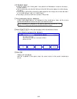
Страница 35: ...Indicates whether the heating unit is activated or deactivated 3 When Activate is pressed the heating unit turns ON Heating unit temperature rises The heating unit state is displayed as Activated 4 When the Deactivate is pressed the heating unit turns OFF Activate Adjust oper checkout Heating unit confirmation Ambient temperature 10 Deactivate Abort Proc status In progress Heating unit temp 20 Hea...

Страница 36: ... and pump One solenoid valve at a time is operated 1 Press Solenoid valve pump test on the maintenance menu The solenoid valve pump test screen is then displayed 2 Press the operation button The operation state of the solenoid valve and pump is then displayed Confirm operation by operation sound Open The solenoid valve is opened Close The solenoid valve is closed Operation The pump is operated Sto...

Страница 37: ...ograms You can confirm version of each program on the screen 1 The maintenance menu is displayed If Prev menu Next menu is not displayed on the maintenance menu set the service personnel maintenance mode on the login user selection screen 2 Mount USB memory containing system data USB port RX2 S RX2 B For precautions when replacing the EZJ126 board refer to 3 3 1 EZJ126 board For precautions when r...

Страница 38: ...wnload procedure please make sure following things before download to avoid such problem Use initialized USB memory with FAT16 or FAT32 when copying system data to USB memory Confirm the USB memory is can be used for download with your machine Please refer the chapter 6 5 21 for troubleshooting OK OK Cancel Download CG font data Correction data Downloaded from USB memory Controller software Print ...

Страница 39: ...ck Operation test the previous calibration Exec time 2015 07 07 11 30 the latest auto replenishment Exec time 2009 07 07 12 45 Start calibration Viscometer calibration HOME Stop 2015 07 07 12 45 Com 0 Plunger falling time Plunger falling time 1st 2nd 5th Average 3rd 4th Ink temperature XX Standard X XXX mPa s X XX sec X XX sec X XX sec X XX sec X XX sec X XX sec 1st 2nd 5th Average 3rd 4th Ink tem...

Страница 40: ...07 07 11 30 the current calibration Exec time 2009 07 07 12 45 Proc Status Ended Viscometer calibration HOME Stop 2015 07 07 12 45 Com 0 Plunger falling time Plunger falling time 1st 2nd 5th Average 3rd 4th Ink temperature XX Standard X XXX mPa s X XX sec X XX sec X XX sec X XX sec X XX sec X XX sec 1st 2nd 5th Average 3rd 4th Ink temperature XX Standard X XXX mPa s X XX sec X XX sec X XX sec X XX...

Страница 41: ...omatically refilled Enable The ink concentration is controlled based on results of the viscosity measurement 1 Press Circulation environment setup Start Continue on the second page of the circulation control menu of maintenance The circulation environment setting screen is then displayed Caution 1 Under ordinary circumstances the default setting of ink concentration control is Enable 2 Enable can ...

Страница 42: ...ce menu is displayed If Prev menu Next menu is not displayed on the maintenance menu set the service personnel maintenance mode on the login user selection screen 2 Press System reset on the second page of the maintenance menu The confirmation message is then displayed 3 Press OK Please wait is displayed After the completion of the system reset the screen returns to the service maintenance screen ...

Страница 43: ...logging data viscosity data ink automatic replenishment data circulation control data fault warning history entry trace data Difference between copy target data maintenance modes User maintenance mode Service personnel maintenance mode Types of data Backup IJP USB memory Data copy USB memory IJP Backup IJP USB memory Data copy USB memory IJP Print data O O O O Standard character O O O O User patte...

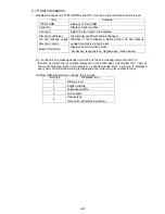
Страница 44: ...Board information Displays board mounting state Model key language key Upgrade key Option board To control ink and makeup usage time limit set Ink and makeup usage time limit to Enable and input the lot number displayed on the bottle label If used after the 1st day of the month following date of manufacture specified usage limit a warning is displayed every hour Note that the warning is displayed ...

Страница 45: ...hine For information on changing to the service personnel maintenance mode refer to 2 1 Setting of service personnel maintenance mode Manual Start up HOME Back Unit information TYPE FORM RX2 BD160W Serial number Ink type JP K69 Lot No Input without hyphens Z999999999 Makeup type TH TYPE A Lot No Input without hyphens Z999999999 Ink viscosity coefficient Prev list Next list 9999 Expiration date man...

Страница 46: ...ring target sensor filtering Normal printing Enable Target sensor is off during target sensor filtering Repeat print stop Sensor chattering happens during target sensor filtering Improper Sensor Position fault occur 5 Print overlap fault check Disable Print Overlap Fault is detected Enable Print Overlap Fault is not detected in error 6 Add items online mode Disable Print items not add when online ...

Страница 47: ...rt the print items will be automatically added 2 Add Items Process The print items will be added Column by Column using the format of the last column such as the number of lines and the character size If there be created the extra Column s and the print item s can t be added in units of Column the print item of the single line 5x8 5x7 character size will be added Please see below the examples when...

Страница 48: ... Transmission Since the print data is re structured by adding the items if the print start signal is inputted right after the data transfer the error Print data changeover in progress will occur Please input the print start signal 400ms after the data is transferred 2 Print Data Recall Transmission The response performance will change whether this function is used or not However if the number of r...

Страница 49: ...Back Repeat print sensor mode Change Character orientation Reverse print Print signal type Print data changeover Char Size menu 1 signal ON OFF ON transition Reverse direction printing right justified left justified print complete print in progress Disable Enable 5x8 5x7 Change mode OFF forward ABC User environment setup Prev set tings Next set tings Char Size menu 2 Excitation V ref warning Produ...

Страница 50: ... HOME Back Minimum character height User environment setup Prev set tings Next set tings 00 0 50 Arabic pattern variation method2 method1 Print Overlap Fault Check Add items in online mode Smile print control Disable Enable Disable Enable Disable Enable Disable Enable Layout display Normal Last printing ...

Страница 51: ...iary functions The language selection screen is then displayed If Change language is not displayed set to service personnel maintenance mode on the login user selection screen 3 Press Change language and select the desired language Selected language is then registered in place of already registered language 4 Select language from registered languages Display language is then changed 5 Select input...

Страница 52: ...mode Languege1 Input mode 1 English Thai Vietnamese Simple Chinese Local language Japanese Local language 2 Traditional Chinese Local language 3 Korean Local language 4 Japanese Local language English Thai Vietnamese Simple Chinese Local language 5 Traditional Chinese Local language 6 Korean Local language 7 Traditional Chinese Local language English Thai Vietnamese Simple Chinese Local language 8...

Страница 53: ... Low M 022 Internal Communication Error S 072 Calendar Content Inaccurate 023 073 024 Ink Heating Unit Over Current 074 025 Ambient Temperature Sensor Fault 075 External Communication Error 032 026 Print controller Cooling Fan Fault 076 External Communication Error 033 027 Print Data Changeover Error C 077 External Communication Error 034 028 Print Data Changeover Error M 078 External Communicatio...

Страница 54: ...or 018 213 115 External Communication Error 019 214 116 External Communication Error 020 215 Upgrade key Failure 117 External Communication Error 021 216 Option Circuit Board Failure 118 External Communication Error 022 217 119 External Communication Error 023 218 120 External Communication Error 024 219 121 External Communication Error 025 220 122 External Communication Error 026 221 Upgrade key ...

Страница 55: ...ff the power and install the EZJ129 board EZJ130 board 2 Turn on the power 3 Insert the USB memory which IJP system data is stored 4 Press Option setup at the second page of the service maintenance work screen If Prev menu Next menu is not displayed on the maintenance menu set the service personnel maintenance mode on the login user selection screen When a USB memory which IJP system data is store...

Страница 56: ...he USB memory 8 Check the function of the software option 2 14 2 Standard communication option setup for RX2 B Refer to 3 3 7 EZJ127 board I O board Procedure to add the option for RX2 B change to EZJ127A board Manual Start up HOME Back 04 05 17 08 Option setup Disable Enable Disable Enable Disable Enable Disable Enable Special communication A External signal A High speed print 18x24 Barcode reade...

Страница 57: ... 1 f 3 f 2 f 1 3 Message length Characters 120 240 1000 Message storage capacity 48 150 Up to 2 000 4 Chimney printing 1 line Available DIN printing 1 line Available 2D code printing Data Matrix QR code Available 5 Number of calendar 2 8 Shift code Available Time count Available Calendar substitution 48 99 Number of counter 2 8 Available when 3 line or 4 line is selected by group 1 Notice 1 Set th...

Страница 58: ...ey DIN print 2D code print NOT supported NOT supported Calendar items Shift code Time count Replacement items Count items 2 NOT supported 48 2 Max registers Max printing columns 48 120 f 1 f 1 5 f 1 66 f 2 f 3 supported supported 8 supported 99 8 150 240 f 1 f 1 f 1 f 1 f 3 150 2000 1000 Number of upgrades available 0 Number of upgrades used 0 Cancel Upgrade code 2 line 12x16 5x5 3 line 18x24 5x5 ...

Страница 59: ...put and print signal is output On the other hand in Short mode to shorten the length of print preparation time it does not perform check of separation timing of these ink droplets However in Short mode and when there is any time of over 640ms with no printing performed the check is performed and even Short mode is set print quality is maintained as long as appropriate printing standby time is save...

Страница 60: ...ontinuous Change unit Encoder Product speed matching None Pulse rate div Factor 0 0 1 1 1 1 999 Enter denominator Repeat print 0 0 0 0 Repeat count 0 99999 SC Repeat intervals Back ABC ABC 9 9 9 9 9 m min Input 0 if unknown 0 0 0 0 0 Line speed Short Time of preparing for printing Standard 3rd screen Displayed when in Service personnel Mode Time of preparing for printing ...

Страница 61: ...r Status color pattern list Status background color IJP Status Status background Pattern A White Stop Green Standby Starting Ink heating Stopping Service Drop adjust Cover open Blue Ready Red Fault Pattern B White Stop Right blue Standby Starting Ink heating Stopping Service Drop adjust Cover open Green Ready Red Fault Keyboard touch can be reduce when Standby Ready change button setting to Enable...

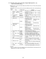
Страница 62: ...operation 1 Setup of expiration date management Open the Unit information screen on Maintenance menu in service personnel maintenance mode If the setup item on the screen Expiration date management of ink and makeup is set to Enable expiration date management of ink and makeup is performed If set to Disable expiration date management of ink and makeup is not performed Default is set to Disable Exa...

Страница 63: ...date of JP K69 24 months Estimated replacement time after opening 6 months Therefore fault output starting date is 30 months from 2014 07 The last day of 2017 01 2017 02 01 b When lot number was input in service personnel maintenance mode Input date of lot number Estimated time to replace is set as fault output starting date Expiration year and date of ink and makeup is ignored Ex JP K69 Year and ...

Страница 64: ...Ink Shelf Life Information Text Replacement of ink is recommended Cause 1 It is estimated time to replace ink 2 Ink lot number is different Solution 1 Use ink within its expiration date at replacement 2 Confirm ink lot number on unit information screen 3 Contact your local distributor Button Close c Guidance of makeup shelf life messages Makeup Shelf Life Information Text Replacement of makeup is ...

Страница 65: ... circulation control menu of maintenance Set Careful Cleaning Stop to Disable Default setting Enable 3 Setup confirmation for Confirmation window for Manual Control Menu Go to Environment setup menu screen and press Touch screen setup Then press Display of Confirmation window for Manual Control Menu If Nondisplay is selected the shutdown process of Careful cleaning is NOT available 2 19 2 Instruct...

Страница 66: ...utton The regular shutdown process with nozzle cleaning is executed by pressing OK button or STOP 2 button 1 If Shutdown Process Confirmation message does not appear go to Item 1 2 below 2 STOP button will only show up with Model RX2 S 1 2 Confirmation of setup items for Confirmation message display of Control menu In case that even the Shutdown button at top right is pressed but Shutdown Process ...

Страница 67: ...ter the start up the ink concentration will become lower gradually by the automatic nozzle cleaning of shutdown process For stable IJP operation when IJP is started please run IJP with ejecting ink for a certain period of time By this IJP operation the ink concentration will be automatically adjusted and its viscosity will recover to the initial state The required run time will depend on the opera...

Страница 68: ... 480 the oldest data is erased 1 Contents of each log file The following examples show the image of the logging data text file is pasted to Microsoft Excel format 1 Fault and warning log ALARM TXT Example Code Log management code of each Fault and Warning Refer to the 2 13 Fault Warning log management code Info1 to 4 Internal management code to specify the cause of alarm Date Time Code Message Inf...

Страница 69: ...plenishment to the initial level 1 Ink replenishment for dot count 1 No makeup replenishment Low Increasing concentration control 1 Ink replenishment for dot count 1 2 Ink replenishment to the initial level No makeup replenishment No replenishment High Reducing concentration control 1 Ink replenishment 2 2 Makeup replenishment to the initial level No replenishment 1 In case of Dot count 65 536 dot...

Страница 70: ...vel is higher than initial level when increasing or reducing concentration control 2 Normal end at Step C1 The main tank ink level becomes higher than initial level after ink replenishment for dot count 4 Normal end at Step C2 5 Normal end at Step C3 Abnormal end or terminated Mode A Abnormal end at step B1 B Terminated at step B1 C Abnormal end at step B2 D Terminated at step B2 E Abnormal end at...

Страница 71: ...bility Instability in the 5 times measurement of falling time The difference between the maximum and minimum values of falling time exceeded 10 of average value 4 Out of range Initial level High speed machine The position of initial level at the high speed machine 1 to 3 0 At the other model Date Time 1 2 3 4 5 Average at falling time Temperature Standard Viscosity Adjustment of viscosity High spe...

Страница 72: ...M clock 2014 01 22 9 20 00 CCPU 2014 01 22 9 20 10 MCPU 2014 01 22 9 20 10 3 003 Select message 2014 01 22 9 25 35 0001 normal Code refer to the next page Sequence name refer to the next page Info1 Info4 refer to the each Logging contents Date Start time Finish timeCode Sequence name Result Aborted step info1 info2 info3 info4 1 2011 7 7 7 05 29 0 02 09 160 Eject ink B 3 0 0 0 0 0 2 2011 7 7 7 06 ...

Страница 73: ...t 3 Select message 15 Ambient temp upper lim 4 Fault warning log clear 16 Excitation V ref Max 5 Set Viscosity 17 Unmatched language key 6 Excitation V 18 Upgrade recovery 7 Serial number changer 19 Print interval mode 8 Unmatched model key 21 Ink Drop Charge Rule 9 CM clock 22 Cable length change 10 Restore 23 Print overlap check change 11 Ink shelf life ...

Страница 74: ...3 Execute double click UXVUP0A22 CJ8reset _1 exe and UXVUP0A22 CJ8reset _2 exe for Create UXVUP folder and cj8resc_rx2 4 Copy the UXVUP folder and cj8resc_rx2 to the USB root directly 2 Rescue procedure 1 Be sure to turn off the power 2 Insert a rescue memory USB into the slot 3 Turn on the power Download procedure start automatically 4 Turn off the power when the download is completed 5 Take the ...

Страница 75: ...ck up data Print data Original shipment state User pattern Original Standard character Original User environment setup Original System environment setup Original Communication environment Original Operation setup Original Reinstall Ink operating time Cumulative op time and Pint count Alarm history All blank Excitation V up data Excitation V ref 11 Touch screen setup Original Circulation control Or...

Страница 76: ...nal control and interior of inlet cover at primary power side When opening the cover of the controller part the engine part and I O part be sure to cut off the power supply And wait for at least 10 seconds before accessing The unit has such a part that high voltage is applied When performing the adjustment in a state where the cover is opened be fully careful about an electric shock Caution agains...

Страница 77: ... bite on the cable Caution against electric shock Caution When opening the maintenance door in a state where the surface of the main body is wet ensure to remove water on the surface to prevent intrusion of the water to inside of the main body and open it softly EZJ119 board Available as option Fixing screw M3x2 EZJ127 board Fixing screw M3x2 IJP LAN UNIT Available on some models as option Fixed w...

Страница 78: ...of the side cover In order to avoid an electric shock be sure to turn off the power supply and wait for at least 10 seconds and pull the power cable out of the outlet before opening the cover It is not necessary to remove Inlet cover or Inlet base when accessing to interior of the side cover Caution when accessing to interior of the side cover Be sure to connect the ground wire before turning on t...

Страница 79: ...oard RX2 B N Y 7 EZJ132 ASSEMBLY Circulation connection board Y Y 8 EZJ112A ASSEMBLY Phase sensor board Y Y 9 EZJ113 ASSEMBLY Power relay board Y N 10 EZJ114A ASSEMBLY LED SW board RX2 S Y N 11 EZJ114B ASSEMBLY LED SW board RX2 B N Y 12 EZJ129 ASSEMBLY SOP terminal board OP N 13 EZJ130 ASSEMBLY SOP controller board OP N 14 EZJ119A ASSEMBLY Relay output board OP OP Component table of the Controller...

Страница 80: ...hen turn on the power with the system data USB memory card inserted Download will be performed automatically 7 After download is completed execute System reset on the second page of the service maintenance screen 8 Confirm Serial number on the Unit information screen and then confirm the date and time 9 Recover the data from the back up memory card by using the copy data function From the USB memo...

Страница 81: ...scosity coefficient on 2 10 Unit information 7 Adjustment of auto phase gain value 2 3 4 Auto phase gain adjustment 8 Excitation voltage setting Service manual 6 10 Excitation Setting Adjustment 9 Readjustment of auto phase gain value 2 3 4 Auto phase gain adjustment 10 Editing print data Instruction manual 4 Editing print data and printing 11 Setting of substitution rules Instruction manual 4 9 3...

Страница 82: ...anel CN4 Connector for LCD harness Connector for EZJ126 board CN8 Connector for battery connection Fixing screw 3 locations Without Fixing screw Fixing screw 3 locations Fixing screw 3 locations Connector for USB F1 F2 IC34 F3 Connector for EZJ 114 board C55 ...

Страница 83: ...ery not used or battery of 3V or more is to be disposed of connect resistor of about 100 ohms between both terminals of battery and discharge for at least 48 hours Then confirm that the battery voltage is less than 3V and insulate electrodes using tape etc before disposal For removed batteries following the warning of Battery Low confirm that the battery voltage is less than 3V before disposal Cau...

Страница 84: ... extraction of flexible flat cable hereinafter referred as FFC 1 How to unlock Press the actuator upward Figure 1 Use your fingernails of thumb or forefinger and handle the actuator like flipping it upward Actuator Figure 1 Do not unlock the actuator by picking up with fingers or do not use tools such as driver to unlock actuator as shown in figure 2 These may lead to a breakage of the actuator Ca...

Страница 85: ...external view RX2 S B LCD replacement procedure 1 Turn off the power and open the maintenance door 2 Remove flexible flat cable from LCD and EZJ128 board 3 Uninstall EZJ128 board 4 Remove attachment for the board 5 Remove LCD by unscrewing LCD fixing screws in 4 locations 6 After replacing install the LCD by performing opposite procedure Figure 4 Insert the FFC in a direction perpendicular to the ...

Страница 86: ... a new touch panel by performing opposite procedure When inserting the touch panel connection cable into the connector of the EZJ128 board hold both sides of the reinforced connecting portion as shown in the drawing and insert it so as not to fold the cable Caution when inserting or extracting touch panel connection cable Touch panel Maintenance door Wear the gloves when replacing the touch panel ...

Страница 87: ...ith system data USB memory inserted Downloading will be performed automatically 10 After turning on the IJP the messages of Memory Fault M Print Data Setting Notice are displayed on screen display Please close the messages to touch the Close button 11 Execute System reset on the second page of the service maintenance screen 12 Confirm Serial number on the Unit information screen and then confirm t...

Страница 88: ... 2 2 System environment setup 5 Excitation adjustment 2 3 1 Excitation adjustment 6 Viscometer calibration or Viscosity coefficient input 2 6 1 Calibration of viscometer or input ink viscosity coefficient on 2 10 Unit information 7 Adjustment of auto phase gain value 2 3 4 Auto phase gain adjustment 8 Excitation voltage setting Service manual 6 10 Excitation Setting Adjustment 9 Readjustment of au...

Страница 89: ... fixing EZJ125 TP321 PGND Connector for battery connection Connector for EZJ125 board Connector for model key Connector for Language key Not mounted on RX2 B Connector for EZJ128 Connector for EZJ130 Not mounted on RX2 B TP323 SGND TP1427 Print in progress TP774 Encoder N TP787 Sensor N ...

Страница 90: ... the power of the IJP and confirm the date and time Perform set up again if it shows wrong date or time Caution With respect to the setting of date and time refer to the Instruction manual 6 2 setting the Date and Time With respect to the replacement procedure of EZJ125 refer to 3 3 6 EZJ125 board With respect to the replacement procedure of EZJ130 refer to 3 3 12 EZJ130 board When replaced with a...

Страница 91: ... the support area are not displayed if the unit information stored in the language key differs from the information stored in the unit Note at the replacement In the event of breakage of language key the key needs to be replaced Do not install any keys removed from other unit Before the replacement be sure to turn off the power Remove the language key from old EZJ126 board and install that key to ...

Страница 92: ... 3 Chimney DIN print 2D code print NOT supported NOT supported Calendar items Shift code Time count Replacement items Count items 2 NOT supported 48 2 Max registers Max printing columns 48 120 f 1 f 1 5 f 1 66 f 2 f 3 supported supported 8 supported 99 8 150 240 f 1 f 1 f 1 f 1 f 3 150 2000 1000 Number of upgrades available 8 Number of upgrades used 0 Cancel Upgrade code QS202 2 line 12x16 5x5 3 l...

Страница 93: ...f the power Set up DSW1 and DSW2 according to the nozzle diameter After replacing the board confirm the charging voltage Perform the excitation adjustment and the auto phase gain adjustment When removing the connector from CN2 CN3 and CN5 hold the socket housing and pull it out in straight Replacement procedure of EZJ125 board 1 Turn off the power 2 Remove the protective cover As the drawing below...

Страница 94: ... APH signal DSW1 Two spacers for fixing a protective cover Two fixing screws TP15 PTC signal LED1 Two fixing screws Two spacers for fixing a protective cover DSW2 Two spacers for fixing EZJ125 board Two spacers for fixing EZJ125 board CN5 CN3 CN2 EZJ125 board EZJ126 board Spacer for fixing the EZJ125 board Push the hook Pull up the EZJ125 board Spacer for fixing the protective cover Pull up the sp...

Страница 95: ...put NPN PNP can be selected by SW2 RX2 S Standard RX2 B Option 5 Signal ground 6 Power supply for encoder Output DC24V 100mA max 1 Totem pole Open collector NPN can be selected by SW1 Power supply can be selected by SW1 7 Encoder signal Totem pole Input 8 Encoder signal Open collector NPN Input 9 Ground for Encoder 10 Ready Output Open collector NPN only 11 Signal ground 12 Fault Output 13 Warning...

Страница 96: ...rocative printing Deflection voltage ON OFF Run Reset Stop Input Output NPN Input Output PNP DSW2 Both of bits are put on the bottom Both of bits are put on the up position Input NPN Output PNP Input PNP Output NPN DSW2 Set only the right bit to the up position Set only the left bit to the up position SW1 Set content Default Bit 1 Setting is performed according to the specification of the encoder ...

Страница 97: ...s lighted LED12 Reset input NPN When the reset signal input NPN is ON it is lighted LED13 Stop input PNP When the stop signal input PNP is ON it is lighted LED14 Stop input NPN When the stop signal input NPN is ON it is lighted LED15 Printing output PNP When the printing in progress printing completed signal output is ON it is lighted LED16 Online output PNP When the online output is ON it is ligh...

Страница 98: ...e size AWG26 to 16 Φ0 5to 1 3 Wire covering to be stripped 8 to 9 mm Two fixing screws Two fixing screws TP6 SW1 LED1 LED4 LED19 Lot number Last digit B Terminal block TB1 13 pins SW1 Two fixing screws SW2 Two fixing screws LED1 LED23 TP6 Terminal block TB1 Lot number Last digit A Terminal block TB1 1 Push 2 Insert Twist the wires ...

Страница 99: ...e setting of SW1 and 2 4 Turn on the power 5 Input a special password for service maintenance mode on the select login user menu 6 Press Option setup button at the second page of the maintenance menu 7 Change the software option 20 Standard communication B to Enable 8 Return to the user maintenance mode on the password protection menu With respect to the setting of service maintenance mode refer t...

Страница 100: ...cabinet 1 5 9 Connector on EZJ127 board 9 pin D sub connector Plug 6 Attaching screw Inch screw Pin number Name Input Output Remarks 1 NC Unconnected 2 RD Input 3 SD Output 4 DTR Connected to DSR on IJ printer 5 SG Ground 6 DSR Connected to DTR on IJ printer 7 RTS Connected to CTS on IJ printer 8 CTS Connected to RTS on IJ printer 9 NC Unconnected The control signals are looped back on EZJ127 boar...

Страница 101: ...3 26 Circuit diagram of EZJ127A ...

Страница 102: ...3 27 Circuit diagram of EZJ127B ...

Страница 103: ...connectors to right places EZJ113 board external view AC power is supplied to the EZJ113 board In order to avoid an electric shock turn off the power and wait for more than 10 seconds pull the plug out of socket and then access the EZJ113 board Caution against an electric shock CN2 Connection to AC power input CN3 Connection to EZJ114 board CN1 Connection to multiple power supply CN4 Connection to...

Страница 104: ...ors CN1 2 3 4 and change EZJ113 board Three fixing spacers and one fixing screw 5 Insert the connectors to right places 6 Place the ground wire terminal around the connecting position then close the side cover When closing the cover be sure not to pinching of wires 7 Connect the ground wire terminal to the ground wire connecting position Inside of side cover CN4 CN3 CN1 CN2 EZJ113 Be sure to conne...

Страница 105: ...f the power Before replacing the board be sure not to supply the electric power to the wires connecting to TB2 EZJ119A board external view Replacement procedure of EZJ119A board 1 Turn off the power and open the top cover 2 Remove the connectors CN7 of EZJ119A board 3 Remove the two fixing screws 4 Install a new EZJ119A board by reversing the above procedure Terminal block TB2 M4 SW3 Ready output ...

Страница 106: ...opens or closes depending on whether the IJ printer is ready When the NC contact break contact is used the ready output signal is disabled The path between the TB2 terminals opens as shown in the table below no matter whether the IJ printer is ready When the NO contact make contact is used the ready output signal is disabled The path between TB2 terminals 1 and 3 opens and the path between TB2 ter...

Страница 107: ... to right places Replacement procedure of EZJ130 board 1 Turn off the power and open the maintenance cover 2 Remove the connectors CN1 CN2 of EZJ130 board 3 Remove one fixing screw 4 Unplug the EZJ130 board from the connector CN10 on EZJ126 board and change the EZJ130 board 5 Install a new EZJ130 board by reversing the above procedure CN2 Connection to EZJ129 board CN1 Connection to EZJ129 board C...

Страница 108: ...3 33 Setting of SW Check point Display of LED etc SW1 Setting of input signal Calendar stop signal Reserve input SW1 Both of bits are put on the up position Set the right bit to the bottom Mark Mark ...

Страница 109: ... TB3 Perform the setting of SW4 to 8 EZJ129 external view Replacement procedure of EZJ129 board 1 Turn off the power and open the top cover 2 Remove two fixing screws 3 Remove the connectors CN8 CN9 CN4 and wires from TB3 4 Install a new EZJ129 board by reversing the above procedure 5 Perform the setting of SW4 to SW8 Inside the top cover upper part of cabinet Two fixing screws EZJ129 board EZJ119...

Страница 110: ... Input Output Remarks 1 NC No connection 2 RD Input 3 SD Output 4 DTR Output 5 SG Ground 6 DSR Input 7 RTS Output 8 CTS Input 9 NC No connection 1 5 9 Circuit board side connector 9 pin D sub connector plug 6 Attaching screw inch screw External device IJ Printer SG 5 SG 8 CTS Input RTS 7 RTS Output CTS 6 DSR Input DTR 4 DTR Output DSR Input RD 2 SD RD Output SD 3 Cable length maximum 5m FG Send da...

Страница 111: ...e number signal bit 5 Input 13 Data message number signal bit 4 Input 14 Data message number signal bit 3 Input 15 Data message number signal bit 2 Input 16 Data message number signal bit 1 Input 17 Data message number signal bit 0 Input 18 Calendar stop Reserve input Input Signal can be selected by EZJ130 SW1 NPN PNP can be selected by SW8 19 Reserve signal ground 20 Reserve input Input 21 Reserv...

Страница 112: ...t 5 Sets the polarity of strobe signal transmitted from host Setting Photo coupler operation voltage level at TB3 pin 8 ON OFF ON Bit 6 Reserve Set to OFF OFF Bit 7 Reserve Set to OFF OFF Bit 8 Sets Power supply ON In case of using Power supply OFF In case of not using Power supply ON SW5 SW5 Description Default Bit 1 Reserve Default setting is right table OFF Bit 2 OFF Bit 3 OFF Bit 4 ON Bit 5 OF...

Страница 113: ...ion Set the right bit to the bottom SW8 Setting it according to the data message number signal connection is NPN PNP and the use of the power supply Default setting is both of bits are put on the up position When supplying power from IJ Printer When using external power supply NPN I F PNP I F NPN I F PNP I F SW8 Both of bits are put on the up position Set the left bit to the bottom Set the right b...

Страница 114: ...is lighted LED14 Data message number signal bit 4 NPN When the data message number signal bit 4 input NPN is ON it is lighted LED15 Data message number signal bit 4 PNP When the data message number signal bit 4 input PNP is ON it is lighted LED16 Data message number signal bit 5 NPN When the data message number signal bit 5 input NPN is ON it is lighted LED17 Data message number signal bit 5 PNP W...

Страница 115: ... bit 11 input PNP is ON it is lighted LED30 Strobe signal NPN When the strobe signal input NPN is ON it is lighted LED31 Strobe signal PNP When the strobe signal input PNP is ON it is lighted LED36 Signal during calendar Updating PNP When the Signal during calendar Updating PNP is ON it is lighted LED37 Signal notifying Completion of signal input PNP When the Signal notifying Completion of signal ...

Страница 116: ...3 41 Circuit diagram of EZJ129 ...

Страница 117: ...the fixing screws 6 positions and remove the side cover It is not necessary to remove the inlet base and inlet cover Caution against an electric shock In order to replace the multiple power supply it is necessary to access inside the side cover which has a portion where AC power is applied The multiple power supply has a portion where high voltage is applied In order to avoid an electric shock tur...

Страница 118: ...stick tape strong power may be needed in the case of removal 10 Remove the connector CN2 and 4 of multiple power supply 11 Install a new multiple power supply by reversing the above procedure Check the clamping position of wire harness and connection of connectors on EZJ126 board CN11 14 20 22 24 Ground wire Yellow green spiral Ground wire Yellow green spiral Inside of side cover RX2 S RX2 B EZJ11...

Страница 119: ...high voltage power supply protective cover 3 Remove the protective cover of high voltage power supply 4 Remove the high voltage power supply Remove the two fixing screws and two fixing spacers 5 Install a new high voltage power supply by reversing the above procedure Check the clamping position of wire harness Caution against an electric shock The high voltage power supply has a portion where high...

Страница 120: ...me plate and harness Replacement procedure of DC fan 1 Turn off the main power and open the maintenance door 2 Remove the DC fan connector CN21 on EZJ126 board Remove the two fixing screws of fan plate 3 Remove the two fixing screws of DC fan then remove the DC fan 4 Install a new DC fan by reversing the above procedure Red wire 24V Black wire GND White wire Sensor output Fan plate Two fixing scre...

Страница 121: ...onnector from ILU Ethernet connection port 3 Remove the wire harness from the connector CN3 on EZJ127 board 4 Remove the ILU from plastic holder in I O area 5 Remove the six wires and connector for EZJ127 board from the ILU 6 Install a new ILU by reversing the above procedure ILU connection specification No Terminal name Connection specification 1 IN 0 Brown wire 2 OUT 0 Red wire 3 24V Orange wire...

Страница 122: ...7 CN2 CN3 CN5 EZJ130 SOP controller board Make up reservoir Terminal block Main power switch EZJ113 Power relay board EZJ114A LED SW board CN4 CN2 CN2 CN4 CN3 CN3 CN1 CN1 Print Head CN1 CN5 IJP LAN UNIT EZJ129 SOP terminal board EZJ119A Relay output board CN10 CN9 CN4 CN8 CN1 CN2 CN3 CN24 CN7 CN2 CN14 CN21 CN12 EZJ132 Ink circulation connection board CN2 CN1 Battery DC fan CN4 CN3 Ink reservoir Ma...

Страница 123: ...2 CN6 CN4 MV1 8 High voltage power supply EZJ125 Nozzle head board CN2 CN1 CN4 CN6 CN7 CN2 CN3 CN5 CN5 Make up reservoir Terminal block EZJ114B LED SW board CN4 CN2 CN3 CN1 Print Head CN1 CN5 EZJ119A Relay output board CN3 CN24 CN7 CN2 CN14 CN21 CN12 EZJ132 Ink circulation connection board CN2 CN1 Battery DC fan CN4 CN3 Ink reservoir Main ink tank EZJ127B I O board CN6 CN5 Main power switch C E O ...

Страница 124: ...ZH9191A Multiple power supply harness assembly J 1N4ZE0003A MGV harness assembly K 2N4ZL2118A Level sensor harness assembly L 1N4ZE0002A Sensor harness assembly M 3N4ZM4183A High voltage harness H assembly N 2N4ZL2144A High voltage harness S assembly O 1N4ZE0066A I O harness assembly P 2N4ZL2139A Connection harness MV assembly Q 2N4ZL2140A Connection harness S assembly R 1N4ZE0067A OP I O harness ...

Страница 125: ...will break the unit See the table below for reference torques Part name used location Companion parts name Companion material Reference tightening torque N m kgf cm Self tapping screw M4X12 attaching pressure system etc ICU base A PBT G30 1 7 0 3 17 3 3 ICU base B PBT G30 1 7 0 3 17 3 3 Main ink tank PP 1 33 0 22 13 6 2 2 Self tapping screw M4X16 attaching solenoid valve ICU base B PBT G30 1 7 0 3...

Страница 126: ...a safe place after removing the connection tube block 2 Remove the ink filter from the fixture and draw it out 3 Remove the fixing screws 2 pieces of the reservoir base and remove the reservoir base Reservoir base Fixing screw Ink reservoir Makeup reservoir Connection tube block Connection tube block Ink filter Holder ...

Страница 127: ...od from the front 1 Perform the operations of 1 to 3 in 4 1 2 Approach to the parts on the front side of the equipment 2 Remove the fixing screws 2 pieces of the unit door and open the unit door Caution Take care not to cause the plumbing tube to be caught Unit door Fixing screw ...

Страница 128: ...4 4 2 Access method from the rear 1 Remove fixing screws 11 positions of the rear cover and detach it Rear cover These two screws can remain loosened ...

Страница 129: ...cetic smell Is there any change of property on the plastic surface If there is any sign of above change the main ink tank 4 2 2 Replacement Procedure 1 Drain the ink in the main ink tank Execute Ink Drainage or drain ink from the drain tube 2 Turn off the power supply 3 Perform 4 1 3 Approach to the parts on the rear side of the equipment 4 Remove the wire connecting part screws 3 positions of the...

Страница 130: ... tank Caution Put wiping paper under the main ink tank to provide for an ink drip 6 Clean the portion stained with ink and then install the main ink tank by reversing the above procedure 7 Perform Ink refill and make sure that there is no ink leak Fixing screw Fixing screw Main ink tank ...

Страница 131: ...r under Pressure reducing valve to provide for an ink drip 4 Replace Pressure reducing valve and the O rings 3 pieces with new ones Caution Make sure to use O rings 4 7 3 pieces 5 Clean the O ring mounting positions of Pressure reducing valve joint PRV with makeup And set the O rings 3 pieces in the mounting positions of Pressure reducing valve joint PRV Pressure reducing valve Pressure reducing v...

Страница 132: ...sure reducing valve joint PRV 7 Mount Pressure reducing valve on Pressure reducing valve joint PRV by Fastening screw M4x16 2 pieces Caution Be careful of the mounting direction of Pressure reducing valve Turn Al mark to the lower side 8 Perform Ink Replenishment and adjust the pressure Make sure that there is no ink leak Fastening screw M4X12 Attaching pin Pressure reducing valve joint PRV Ink ci...

Страница 133: ...g the ICU joint at occurrence of damage 1 Mount the O ring on the ICU joint 2 Get the O ring wet with the makeup and then insert it into the connecting port of the circulation unit Caution If it cannot be inserted smoothly the O ring may bite Perform the operations starting from Step 1 once gain 3 Tighten the fixing screw Procedure for removing the ICU joint at occurrence of damage 1 Remove the fi...

Страница 134: ...he filter joint nut and remove the whole from the mounting part 2 Fix the end of the filter joint and loosen the tube block 3 Pull out the tube Assembling the filter joint 1 Mount the O ring on the filter joint 2 Get the O ring wet with the intensifier and install the ink filter and others together with the filter joint nut 3 Pass the tube through the tube lock 4 Insert the tube into the end of th...

Страница 135: ...Execute Gutter Cleaning No operation is required Take care about an ink drip MV4 Execute Ink drainage No operation is required Take care about an ink drip MV5 Execute Nozzle backwash No operation is required Take care about an ink drip MV6 Execute Ink drainage No operation is required Take care about an ink drip MV7 Execute Ink drainage Drain the ink in the main ink tank from the drain tube MV8 Ex...

Страница 136: ...ned with ink and then install a solenoid valve by reversing the above procedure Caution Set the O ring in the groove of the solenoid valve securely Take care not to cause the O ring to fall off or bite 7 Reset the time of the corresponding solenoid to 0 on the Parts usage time management screen Fixing screw Solenoid valve O ring S16 O ring 4 7 O ring mounting groove ...

Страница 137: ...e rear side of the equipment The reason is that the connector is provided on the rear side of the equipment 4 Remove the connector of the pressure sensor 5 Remove the screws 2 positions that fix the pressure sensor The pressure sensor can be removed Caution Put wiping paper under the solenoid valve to provide for an ink drip Connector for the pressure sensor Pressure sensor Unit door Fixing screw ...

Страница 138: ...y ink wet the new O ring with makeup and mount on the joint 8 Insert the pressure sensor and fasten to the joint with the fastener that was removed in step 6 Caution Use a new O ring Mount carefully so the O ring does not fall out or catch 9 Return the unit to its original state by performing the procedure in reverse order 10 Dispense ink and make sure the ink pressure is normal Joint Fastener Pre...

Страница 139: ...ch to the parts on the rear side of the equipment 4 Remove the wire connecting part screws 3 positions of the liquid level sensor in the main ink tank and the exhaust tube 5 Remove the plumbing tubes 13 positions that are connected to the circulation unit Caution Take care about an ink drip Fixing screw Exhaust tube Black White Blue Main ink tank ...

Страница 140: ...sensor 8 Remove the fixing screws at 4 positions that fix the circulation unit The circulation unit can be removed 9 Clean the portion stained with ink and then install the main ink tank by reversing the above procedure 10 Perform Makeup refill and then Ink refill Make sure that any ink or makeup leak does not occur at each connecting part Fixing screw Fixing screw 5 positions 1 position 8 positio...

Страница 141: ... Turn off the power supply 3 Perform 4 1 3 Access to the parts on the rear side of the equipment 4 Remove the clamps 3 positions that fix the wires 5 Remove the connectors of the electric parts 7 positions motor pressure sensor viscometer 3 positions level sensor and float sensor 5 positions 1 position 1 position ...

Страница 142: ...ump unit on the door Remove the ICU joint to remove the tube shown by dashed line and loosen the tube lock to remove the others 7 Remove two 2 screws which are located topside and which are fixing Pump unit to ICU Fixing plate Pull out seven 7 connectors Tube Remove the ICU joint Tube Fixing screw Fixing screw Fixing screw Fixing screw ICU fixing plate Pump Unit ICU fixing plate ...

Страница 143: ... ink drip 9 Clean the portion stained with ink and make sure that the O rings 4 positions are securely mounted in the concave parts of the lower side circulation unit Then install a pump unit by reversing the above procedure 10 Perform Ink refill and adjust the pressure Make sure that there is no ink leak 11 Reset the pump time to 0 on the Parts usage time management screen Fixing screw 8 position...

Страница 144: ...m 4 1 3 Approach to the parts on the rear side of the equipment 3 Remove the connector from the Motor 4 Remove the screws 4 positions that fix the motor The motor can be removed The motor and the spacer are joined Unit door Motor Fixing screw Motor Spacer Pump Unit Motor connector ...

Страница 145: ...in the direction of the chart below 6 Install a new motor by reversing the above procedure CAUTION Beware of Motor Rotation When checking the motor with IJP door opened watch the motor rotation winding Pump Unit Spacer Fixing screw Motor Spacer Pump Unit Board shall be placed at the bottom ...

Страница 146: ... recovery is made b Disassemble and clean viscometer Proceed with c if no recovery is made c Replace viscometer 2 Viscosity Readings Out of Range Estimated cause Ink adhered to the IN side of viscometer Troubleshooting Disassemble and wash viscometer Estimated cause Proximity sensor was faulty Troubleshooting Replace proximity sensor If there is no recovery with the above troubleshooting replace t...

Страница 147: ...meter A Turn power on B Use Solenoid Valve Pump Test screen of Maintenance Work to turn on the pump to MV4 in that order and operate them for at least 10 seconds The ink remaining in viscometer will return to the main container C Turn power off 3 Unplugging connectors Caution Do not perform this work with power turned on Doing so will cause Viscometer Temperature Sensor Fault to occur Unplug the c...

Страница 148: ...ut to the wiping paper 3 Make sure that no ink remains in viscometer and then pull out the cylinder If ink remains it will dirty the coil 4 Put the removed plunger and cylinder in a beaker filled with intensifier and wash them for at least 5 minutes using an ultrasonic washer Viscometer cover Three viscometer cover setscrews Coil Cylinder Plunger Two viscometer IN joint setscrews Thermistor setscr...

Страница 149: ...dure 1 Set the O ring and squeezing pin on the viscometer OUT side and use the two setscrews to attach them to the circulation unit 2 Plug in the connectors of lead wires again 3 Connect the viscometer IN side tube mark G Caution After reassembly it may be necessary to replace the ink and or calibrate the viscometer When disassembling and washing during installation Calibrate the viscometer withou...

Страница 150: ... its original position referring to item 4 9 4 Take care not to forget to plug in the connectors of lead wires Caution After replacing the proximity sensor it is necessary to replace the ink and calibrate the viscometer see 2 6 Calibration of viscometer 4 9 6 Replacing thermistor 1 Remove the viscometer from circulation unit referring to item 4 9 1 2 Remove the screw holding the thermistor fixing ...

Страница 151: ...onnectors 4 locations 5 Remove the piping connections 4 positions with the print head Loosen the tube lock and pull out the tube Caution Put wiping paper at the end of the tube to provide for an ink drip Circulation line Pipe signal J Recovery line Pipe signal A Supply line Pipe signal E Makeup line Pipe signal R Clamp Fastening screws 4 locations The inside of a side cover RX2 S RX2 B FG line CN5...

Страница 152: ...y and remove it from the harness of the print head Fastening screws 11 locations Fastening screws Fastening screws Fastening screws screws Fastening screws Head H Clamp assembly assembly Note Follow the reverse orders as shown in the figures above when you mount the cable Head H Clamp assembly assembly High voltage line White Video signal line Black Cable Signal 3 Excitation line Black Cable Signa...

Страница 153: ...nstalled into the printer please install it as 14 core cable the thickest cable shall be placed at the most right end when viewed from the rear of the printer Please see the figure above 13 Perform Ink Replenishment and adjust the pressure Make sure that there is no ink leak 14 Perform Excitation adjustment and Auto phase gain adjustment 14 core cable shall be placed at the most right end Fastenin...

Страница 154: ...it The check valve is dry or sticks The solenoid valve is operated but ink does not flow Refer to 4 12 Repairing method when the circulation route dry or sticks The solenoid valve malfunctions MV1 malfunctions When Open is executed on the Solenoid Valve Pump Test screen no operation sound is produced Replace or repair the solenoid valve MV1 Refer to 4 12 Repairing method when the circulation route...

Страница 155: ...alve MV9 The pressure resistance of MV6 is faulty When the pump and then MV1 are turned on ink flows to the collation tube Solenoid Valve Pump Test screen Replace the solenoid valve MV6 Others The pressure sensor malfunctions Ink jets and printing can be performed but the pressure value is abnormal Replace the pressure sensor Ink Over Fill often occurs The solenoid valve malfunctions The pressure ...

Страница 156: ...nctions MV4 malfunctions When Open is executed on the Solenoid Valve Pump Test screen no operation sound is produced Replace or repair the solenoid valve MV3 Refer to 4 12 Repairing method when the circulation route dry or sticks The circulation route clogs Clogging in the pipe or joint The nozzle can be flushed reversely and MV4 can be operated normally Refer to 4 12 Repairing method when the cir...

Страница 157: ...p and then Open of MV1 and MV6 are executed on the Solenoid valve pump test screen the ink does not flow Refer to 4 12 Repairing method when the circulation route dry or sticks MV2 malfunctions When Open is executed on the Solenoid Valve Pump Test screen no operation sound is produced Replace or repair the solenoid valve MV2 Refer to 4 12 Repairing method when the circulation route dry or sticks M...

Страница 158: ...nnector is abnormal Part Check method Criterion Pump motor 1 Operate the pump on the Solenoid Valve Pump Test screen 2 Measure the voltage at pin No 5 wire red 20 V DC or more Solenoid valve 1 Replace the solenoid valve and the connector with another normal solenoid valve and connector 2 Make a check on the Solenoid Valve Pump Test screen Release the solenoid valve An operation sound can be confir...

Страница 159: ... the Solenoid Valve Pump Test screen If an operation sound can be confirmed the repair work is completed If not replace the solenoid valve 4 12 2 Repairing method for the supply pump 1 Remove the tube connecting block of the ink reservoir and connect the hand pump 2 Operate the pump MV2 and MV6 in this order on the Solenoid Valve Pump Test screen 3 Apply pressure with the hand pump 4 If the makeup...

Страница 160: ...or Eject ink 2 After the pump is started operate it for about 10 minutes in the status where the pressure adjusting knob is turned completely clockwise to obtain the maximum pressure 3 Stop the pump and then execute Nozzle Backwash If suction from the nozzle can be confirmed the repair work is completed If the pump cannot be repaired repeat the same operations starting from 1 again If the pump can...

Страница 161: ...ower 2 Loosen the screw and remove the intake fan cover 3 Remove the air filter Note The air filter has front and rear faces Set the filter with red mark being invisible Air filter Red mark in rear Intake fan cover assembly Intake fan Screw Air filter Intake fan unit assembly Intake fan cover Intake fan cover assembly Screw 2 locations ...

Страница 162: ... assembly 7 Remove the intake fan unit on two positioning bosses and pull out the harness 8 Install the new intake fan unit by reversing the procedures above Positioning bosses two locations Harness routing Intake fan harness 冷却ユニットクミ Intake fan cover assembly Intake fan unit assembly Fastening screws 4 locations Intake fan unit assembly Fastening screws 4 locations ...

Страница 163: ...ery two times 1 Turn off the power supply 2 Remove the exhaust cover 3 Remove the fixing screws 4 locations the filter cover and the R air filter 4 Install a new R air filter by reversing the above procedure The red mark side is the filter cover side Exhaust cover Fixing screw 4 locations Exhaust cover Red mark Filter cover Fixing screw 4 locations Filter cover R air filter Wire mesh filter There ...

Страница 164: ...4 40 5 Reset the time of the R air filter to 0 on the Parts usage time management screen ...

Страница 165: ...please check the items below 1 Is there any wiring routed around the exhaust duct such as the power cord the electrical signal wirings etc Should there be a liquid spill the wire covering may get cracked Please reroute the wiring and call customer s attention 2 Is there any track of the liquid spill Please propose a tray for a liquid spill to a customer There may be a possibility that the ink make...

Страница 166: ...tch connector Cover switch Video signal line High voltage line APH board APH sensor Shutoff valve MV9 connector Shutoff valve MV9 Air purge tube Nozzle ground Nozzle Nozzle excitation connector Charged electrode Positive deflecting electrode Negative deflecting electrode Gutter APH shield plate Coupling Coupling cover ...

Страница 167: ...hanged as shown in the following figure The customer should not attempt to run the cable himself The cable should be run by a service technician 1 Remove the 4 fastening screws Pull out the coupling approximately 10 mm 2 Turn 90 3 Tighten the 4 fastening screws Coupling ...

Страница 168: ... Following configuration differs according to the type of machine 5 3 2 Replacement method 1 Remove the 2 fastening screws 2 The gutter base and APH shield plate come off Note The packing consists of a combination of 2 types With membrane 9 O ring 1 6 APH shield plate O ring 2 2 ...

Страница 169: ... Remove the lead wire of the nozzle and air purge tube 4 Remove Screw A 1 location and remove the coupling cover 5 Remove Screw B 1 location and Screw C 2 locations Remove MGV holder and nozzle In joint holder Lead wire Coupling cover Nozzle In Joint holder 3 P ツ ギテオサエ MGV holder Air purge tube MV9 filter ...

Страница 170: ...om the MV9 filter then remove O ring 3 9 Fix a new MV9 filter and O ring 3 9 Perform the assembly after dipping the O ring in makeup and confirm that the O ring does not jump out of the hole 2 Attach each cover MV 9 MV9 filter Nozzle IN joint O ring 3 9 ...

Страница 171: ...e connector 4 Remove the nozzle lead wire and the air purge tube 5 Remove Screw A 1 location and remove the coupling cover 6 Remove Screw B 1 location and Screw C 2 locations Remove MGV holder and nozzle In Joint holder 3Pツギテオサエ Shutoff valve connector Air purge tube MV9 Lead wire Coupling cover MGV holder Nozzle In Joint holder 3 P ツ ギテオサエ ...

Страница 172: ...ing does not jump out of the hole 2 Connect the makeup IN joint to the shutoff valve and fix it to the boss on the heating unit 3 Put the makeup in joint in the groove of MGV holder 4 Attach the MGV holder and fix the shutoff valve 5 Put the MV9filter O ring3 9 nozzle In joint and nozzle In joint presser foot 6 Assemble the shutoff valve connector 7 Spurt ink after the assembly and confirm that th...

Страница 173: ... the air purge tube 4 1 Remove Screw A 1 location and remove the coupling cover 2 Remove the heating unit joint presser foot and remove the ink supply tube E 5 Remove Screw B 1 location and Screw C 2 locations Remove MGV holder and nozzle In Joint holder Air purge tube Lead wire MGV holder Coupling cover Nozzle In Joint holder 3 P ツ ギテオサエ ...

Страница 174: ...r cover 8 screws 8 Remove the connector and remove the heating unit 9 Prepare a new heating unit and put an O ring1 7 in the terminal area of the ink supply tube E Perform the assembly after dipping the O ring in makeup and confirm that the O ring does not jump out of the hole 10 Attach the heating unit MV 9 Heating unit Heating unit Connector ...

Страница 175: ...the connectors 2 locations 6 Remove the APH sensor When returning to the original state remove the gutter base fasten the APH board and then re attach the gutter base in order to enhance O ring assembly reliability of the APH sensor 7 Perform the automatic phase gain adjustment Gutter base O ring 2 2 APH board Fastening APH sensor Connector Connector ...

Страница 176: ...ode fastening screw C 5 Cut the nozzle side of Nozzle out joint with cutter knife etc Caution when removing the nozzle OUT joint remove it so as not to pull the main body side tube Caution 1 If you scratch the coupling with a cutter or the knife it may cause an ink leaking and so on 2 When removing a cut piece of the tube cut the tube piece and pull it off the coupling Nozzle excitation connector ...

Страница 177: ... imperfect ink will below off 8 Cut the recovery side tube of the new nozzle into a suitable length and connect the nozzle OUT joint Caution 1 Get rid of the tube remaining on the joint in the 5 2 When the tube is hardly put in the joint because it slips grasp the front edge of the tube by a JK wiper or the like and put it in the joint 9 Put the charged electrode in the new nozzle and fix the vide...

Страница 178: ...sonic cleaning with MEK or genuine Makeup to remove ink component and other soluble substances in solvent 2 Drying by air blow or leaving it for 3 to 5 minutes to remove the solvent on the orifice surface 3 Ultrasonic cleaning with Weak Alkali Detergent for 30 minutes to remove the foreign objects that cannot be removed by MEK or Makeup See 1 above 4 Ultrasonic cleaning with water pure water 2 for...

Страница 179: ...s 45 kHz the change in surface of the aluminum foil may not appear Figure 1 Example Placing aluminum foil in the ultra sonic cleaning machine Photo 1 Status of aluminum foil after 1 minute ultra sonic cleaning 2 Notice etc 1 The material of the inner tank should NOT be made of resin Either SUS or Glass is preferred Its thickness shall be thin Because the sound wave is absorbed reduced 2 The up and...

Страница 180: ...1 Pump Motor Fault 6 2 22 Viscometer Ink Temperature Sensor Fault 6 2 23 Ink Heating Unit Temperature Low 6 2 24 Model key Fault 6 2 25 Language key Fault 6 2 26 Charge Voltage Too Low 6 3 Faults Print stop type 6 3 1 Ink Drop Charge Too High 6 3 2 Barcode Short On Numbers 6 3 3 Shutdown Fault 6 3 4 Count Overflow 6 3 5 Print Overlap Fault 6 3 6 Print Head Cover Open 6 3 7 Improper Sensor Position...

Страница 181: ...25 6 5 Faults No on screen indications 6 5 1 Chipped print lower dots 6 5 2 Chipped print upper dots 6 5 3 Varying character height 6 5 4 Increased character distortion 6 5 5 Disordered characters 6 5 6 Ink leakage blowout Print head 6 5 7 Printing initiation failure in ready state no prints 6 5 8 No ink ejection from nozzle 6 5 9 Freeze of display 6 5 10 Problems due to inappropriate ink stream p...

Страница 182: ...makeup Yes No Return the sensor section to its position Return the sensor section to its position Ink Low Is the fault cleared by pressing the Clear key Is an insoluble substance deposited on the sensor No Remove and joint the following connectors EZJ126 CN13 EZJ132 CN1 CN3 Is the fault cleared by power on reset END 1 OK Yes 3 Is the connection harness conducting Replace the harness 2 NG Replace t...

Страница 183: ... cover Turn OFF the power and then pull out the sensor No Is the initial level sensor ON No Replace the EZJ126 board Yes Is there a creepage leak between the ground electrode and the over fill electrode of liquid level detection of the main tank Check it by mounting and removing the harness Remove the ink adhering onto the creepage surface between the two electrodes Or replace the sensor part of t...

Страница 184: ...isconnected Connect the connector Disconnect the connector and then reconnect it Does the printer become ready for printing Yes No No Replace the high voltage power supply unit Does the printer become ready for printing Yes No Replace the EZJ125 board END Does the printer become ready for printing Yes No Replace the EZJ126 board END Yes END ...

Страница 185: ...es No Does the MV2 Replenishment valve operate on the solenoid valve pump test screen Does the MV2 operate when Other operating solenoid valve connector joints to MV2 Repair the sticking or replace the solenoid Disconnect the connectors then reconnect them 3 connectors Connect the connector Is the EZJ126 board CN13 or EZJ132 board CN1 3 connector disconnected Is the connection harness conducting R...

Страница 186: ...r the makeup over the charge electrode and nozzle area to clean them and allow them to thoroughly dry Is the cumulative ink use time longer than the useful ink life Replace the ink Yes Yes Yes No No Is the ink drop shape good Change the excitation voltage setting to assure proper ink drop shape No Yes Is the nozzle clogged or the ink stream bent 1 No Replace the EZJ126 board Remove the orifice pla...

Страница 187: ...ation error C M S Are the nozzle head and IJ printer main body insulated from the other equipment Is the IJ printer connected to its dedicated ground Clear the fault Restart the IJ printer Replace the EZJ126 board Replace the multiple power supply Does the fault recur ノ イ ズエラ ーが 発生する か Replace the EZJ128 board EZJ128 基板を交換する Noise Fault C ノ イ ズエラ ーC Yes Used the SOP05 for call up print data Yes Th...

Страница 188: ...o Yes Yes Is the ink recovered without filling the gutter hole with the ink Yes No Yes Does the ink stream enter the center of the gutter Adjust the ink stream position No 1 Press the Clear key to clear the fault Press the Start up key to restart the IJ printer Press the Clear key to clear the fault Press the Start up key to restart the IJ printer See section 6 5 8 No ink suction from gutter Are t...

Страница 189: ...ssued Has the ink makeup entered inside the nozzle head rear cover Wipe the entered ink makeup away with JK wiper and allow inside print head rear cover to thoroughly dry Yes No Replace the ink Replace the EZJ125 board Resume the operation No Yes Is the alarm issued Replace the EZJ126 board Resume the operation Yes No Is the high voltage line dusty Wipe and clean the dust off the line and allow to...

Страница 190: ...e out fault recur Yes No Does the MV7 Makeup valve operate on the solenoid valve pump test screen Does the MV7 operate when other operating solenoid valve connector joints to MV7 Replace the solenoid Is the connection harness conducting Replace the harness Replace the EZJ126 board Is the fault cleared by power on reset Does the initial level sensor operate Yes No Does the Replenishment Time out fa...

Страница 191: ...rall wiring diagram Turn OFF the power Yes No No Yes Yes Connect the sensor connector No Is the fault cleared by power on reset Is the connection harness conducting Replace the connection harness END Yes Yes No OK NG END Replace the sensor Replace the EZJ126 board Is the fault cleared by power on reset No Disconnect the connectors then reconnect them 3 connectors Connect the connector Is the EZJ12...

Страница 192: ...erating mode Restart the IJ printer Ink Heating Unit Too High See Section 6 5 8 No ink ejection from nozzle Does the ink jet out Yes No Disconnect EZJ125 board CN7 connector and reconnect it Replace the heating unit Replace the EZJ125 board Does the fault recur Yes No Resume the operation Does the fault recur Yes No Clear the fault From the maintenance screen place the heating unit in the operatin...

Страница 193: ...onnector Multi DC Power Supply Fan Fault Is the multiple power supply fan running No Is the EZJ126 CN2 connector or multiple power supply CN4 connector disconnected Yes Replace the multiple power supply No END Is the problem fixed No Yes Replace the EZJ126 board ...

Страница 194: ...move the print head cover Pour the makeup over the charge electrode area to clean it Yes Replace the EZJ126 board No Does the printer become ready END Yes Replace the print head No Does the printer become ready Replace the EZJ125 board Does the printer become ready Yes No Replace the multiple power supply Does the printer become ready Yes No ...

Страница 195: ...blem fixed No Yes Replace the high voltage power supply Is the ink stream being ejected from the nozzle Refer to 6 5 8 No ink ejection from nozzle Refer to 6 2 5 Ink Drop Charge Too Low Yes No END Is the problem fixed No Yes Replace the EZJ125 board Replace the print head END Is the problem fixed No Yes Replace the EZJ126 board Is the gutter section soiled No Refer to 6 2 5 Ink Drop Charge Too Low...

Страница 196: ...the Instruction manual Caution Ink Heating Unit Temperature Sensor Fault Disconnect the EZJ125 board CN7 connector and reconnect it Replace the heating unit Replace the EZJ125 board Resume the operation Yes No Clear the fault From the maintenance screen place the heating unit in the operating mode Restart the IJ printer Does the fault recur Yes No Replace the EZJ126 board Does the fault recur Clea...

Страница 197: ...ation Memory Fault OP Does the fault recur when the EZJ130 board is attached No Yes Replace the EZJ130 board Memory Fault M S Resume the operation Does the fault recur upon power on reset No Yes Memory Fault C Does the fault recur upon power on reset No Yes Replace the EZJ126 board Replace the EZJ128 board Does the fault recur Do the system reset by rescue soft Yes No Do the system reset by rescue...

Страница 198: ...ion Ink Heating Unit Over Current Is the PTC resistance measured between the EZJ125 board TP3 and TP15 lower than 23 No Yes Replace the heating unit Replace the EZJ125 board Does the fault recur Yes No Clear the fault From the maintenance screen place the heating unit in the operating mode Restart the IJ printer Replace the print head Does the fault recur Yes No Resume the operation Replace the EZ...

Страница 199: ...or and reconnect it Replace the print head Replace the EZJ126 board Resume the operation Does the fault recur Yes No Does the fault recur Yes No Cooling Fan Fault Disconnect the EZJ126 board CN21 connector and reconnect it Replace the EZJ126 board Resume the operation Replace cooling fan Does the fault recur Yes No Does the fault recur Yes No ...

Страница 200: ...ult recur Pump Motor Fault Pull out and insert the connector CN13 of the EZJ126 board CN1 and CN3 of the EZJ126 board pump motor connector Replace the EZJ126 board Resume the operation Replace the pump motor Does the fault recur Yes No Yes No ...

Страница 201: ...5 board Is the fault issued again Yes No Resume the operation Is the fault issued again Yes No Replace the EZJ126 board Is the fault issued again Yes No Viscometer Ink Temperature Sensor Fault Replace the thermistor Replace the EZJ126 board Resume the operation Does the fault recur Yes No Does the fault recur Yes No Disconnect and reconnect the following connectors EZJ126 CN13 EZJ132 CN1 3 Thermis...

Страница 202: ...place the EZJ126 board Does the fault recur Yes No Resume the operation Does the fault recur Do the system reset by rescue soft Model key failure Does the fault recur after disconnect and reconnect the model key to EZJ126 board CN15 It is necessary to change the model key Contact your local Hitachi sales office with the unit serial number and model name No Yes Replace the EZJ126 board Does the fau...

Страница 203: ...oo Low Does the fault recur Replace the EZJ125 board Replace the EZJ126 board Does the fault recur Does the fault recur No No No Yes Yes Yes Clear the fault Place the printer in The Ready state Replace the high voltage power supply Resume the operation ...

Страница 204: ...oper ink drop shape Refer to 6 5 18 No ink suction from gutter No Eliminate the cause of vibration or shock Does the IJ printer become ready for printing when you eject ink and start the IJ printer with the high voltage power supply unit high voltage output FASTON terminal disconnected Replace the high voltage power supply unit Has the ink makeup entered inside the print head rear cover See the se...

Страница 205: ...nal 13 Refer to the Instruction Manual 4 13 3 Set various printing 6 3 3 Shutdown Fault Barcode Short On Numbers Input the fixed number of character for EAN 13 EAN 8 UPC A UPC E Resume the operation Shutdown Fault Disconnect the EZJ113 board CN4 connector and EZJ126 CN20 connector and reconnect them Replace the EZJ113 board No Resume the operation Is the fault issued again Yes Replace the EZJ126 b...

Страница 206: ...ration to 9 ms or longer Set the repeat printing intervals to the printing time plus 9 ms or longer Replace the EZJ126 board No Yes Yes Yes No Perform sensor filter setup Yes No Resume the operation Is the print start signal chattering Are the repeat printing intervals less than the printing time plus 9 ms with the repeat printing mode selected No Count Overflow In case of count multiplication pri...

Страница 207: ...he head cover damaged or missing Properly install the magnet Yes Yes Yes No No Is the EZJ125 board CN7 connector disconnected Connect the connector Replace the EZJ126 board No Yes No Open the print head rear cover and position the magnet close to the cover switch Does the cover switch conduct Press the Clear key to clear the fault Resume the operation Replace the cover switch No Yes Print Head Cov...

Страница 208: ...ting function required No Set the Repeat count to 0000 Replace the EZJ126 board Yes No Resume the operation Decrease the clearance between the print head and print target detector Yes Ensure that the print start signal does not chatter any longer Yes No Is the print start signal chattering No Is the Repeat count is set to 0000 from the print specifications screen ...

Страница 209: ...setting is greater than necessary for the sensor normal ON time Select a setting that is greater than necessary Does the sensor turn ON and OFF Clean the sensor to eliminate any obstacle Replace the sensor No Yes No If the problem is not fixed Yes No No Yes Replace the EZJ127 board Replace the EZJ126 board Yes Clear the fault Resume the operation Is there any dirt buildup or other obstacle on the ...

Страница 210: ...ween the sensor and print head and reduce the number of workpieces between the sensor and print head to four or less Yes The print target detection signal entered while the printer was not ready See that the print target detection signal enters after a while SUPPLEMENT Print Data Changeover In Progress Resume the operation There is a way to set the item Print data changeover on User environment se...

Страница 211: ...s having differing formats is reduced to eight or less Yes No Resume the operation SUPPLEMENT Columns differing in the line count line spacing or dot matrix will be handled as different formats Blank Print Items Does any print item consisting of Blank characters alone exist Adjust the print contents so that print items consisting of Blank characters only no longer exist Yes No Resume the operation...

Страница 212: ...tor is disconnected and then reconnected Replace the EZJ128 board EZJ128 基板を交換する Yes Yes Resume the operation Replace the EZJ126 board Does the fault recur Yes No Used the SOP05 for call up print data Yes The strobe input timing is following the regulation No Input the strobe signal with correct timing of the SOP05 instruction No Does the fault recur Yes Yes No Does the fault recur Does the fault ...

Страница 213: ...r was not ready See that the print target detection signal enters after a while SUPPLEME NT Invalid Timing Resume the operation Ink Shelf Life Information Use ink within its expiration date at replacement and input the ink lot number on unit information screen Resume the operation Makeup Shelf Life Information Use makeup within its expiration date at replacement and input the makeup lot number on ...

Страница 214: ...e More detail refer to the manual 4 8 Set the print format Free layout RX2 S only Note Free layout printing failure Delete the specific print items or Decrease the Ink drop use rate ex 1 2 1 3 Does the fault recur No Yes Resume the operation ...

Страница 215: ...essage again after system initialization Does the fault recur Is the EZJ126 board CN1 connector disconnected Connect the connector Replace the EZJ126 board Yes Yes Replace the EZJ128 board Yes No Yes Connect the connector No No No No Yes Copy the data from USB to IJP 戻す Is the EZJ126 board CN1 connector disconnected Does the fault recur Does the fault recur Resume the operation ...

Страница 216: ...scometer operation test on the Circulation system control screen Replace the viscometer filter Disassemble and clean the viscometer Replace the viscometer Is it normally measured Is it normally measured Yes Yes No No Viscosity Reading Instability during installation calibration Re execute viscometer calibration 2 3 times Does calibration finish normally No Yes Press OK then the coefficient is dete...

Страница 217: ...tion Perform the viscometer operation test on the Circulation system control screen Disconnect and reconnect the following connectors EZJ126 CN13 CN22 EZJ132 CN1 to 4 Proximity sensor MV10 Disassemble and clean the viscometer Replace the viscometer Is it normally measured Is it normally measured Yes Yes No No Replace the ink Is it normally measured Yes No ...

Страница 218: ...k reservoir Replace the ink Has the viscosity increased Yes No Operate the printer for an hour or so and check the ink viscosity Low Ink Viscosity Resume the operation Is the printing quality normal Yes No Check the printing quality Replace the ink in the ink reservoir Replace the ink Has the viscosity decreased Yes No Operate the printer for an hour or so and check the ink viscosity ...

Страница 219: ...d and then reconnected Yes Replace the EZJ126 board Does the fault recur No Calendar Content Inaccurate Resume the operation Is the EZJ128 board CN8 connector or EZJ126 board CN14 connector disconnected or in poor contact Yes No Replace the batteries in the controller engine section Normality is restored when the connector is disconnected and then reconnected Yes Replace the EZJ128 board Does the ...

Страница 220: ...ime set to 0 from the operation management screen when the ink was replaced last Replace the ink and set the Ink operating time to 0 from the operation management screen Enter the cumulative ink ejection time elapsed since last ink replacement in the Ink operating time field of the operation management screen Enter the standard ink life limit value in the Ink alarm time field of the operation mana...

Страница 221: ...he connector Yes No Yes No Replace the EZJ125 board Is the Ambient temperature upper lower limit value erroneously set Properly set the Ambient temperature upper lower limit value Use an air conditioner or the like to ensure that the IJ printer ambient temperature is within the operating temperature range No Yes Is the problem fixed No Yes Replace the print head END Is the problem fixed No Yes Rep...

Страница 222: ...dard value by the pressure reducing valve Check the indicated value and standard value of the ink pressure on the Operation management screen Can the pressure be adjusted by the pressure reducing valve Replace the pressure reducing valve Replace the pressure sensor Is the warning released Yes Yes No No Yes No Can the pressure be adjusted by the pressure reducing valve ...

Страница 223: ...ration Is the EZJ128 board CN8 connector disconnected or in poor contact Yes No Replace the battery in the controller section Normality is restored when the connector is disconnected and then reconnected Yes Replace the EZJ128 board Does the fault recur No ...

Страница 224: ... repair the supply pump Does ink flow into main tank when operating pump MV1 MV6 No Does ink flow into main tank when operating pump MV2 MV6 Replace or repair the CV assembly Replace the three way valve filter Yes Replace the viscometer filter No No Yes Can the pressure be adjusted by the pressure reducing valve No No Yes Yes Can the pressure be adjusted by the pressure reducing valve Can the pres...

Страница 225: ...ave disconnection or damage Does the fault recur Does the fault recur recur Replace Sensor Harness RX2 Cooling Fan Warning No Yes No Yes Product Speed Matching Error Resume the operation The frequency of the encoder signal is exceeding the printing capability of the IJ printer Lower the frequency of the encoder signal or increase its dividing ratio Note that the printed character width will change...

Страница 226: ...e setting is within the specified limits Direction of deflection Missing dots Gutter Ink foreign matter Print drop Chipped print Replace the ink Adjust the ink stream position so that the ink stream is centered with respect to the gutter No Is the ink stream positioned at the center of the gutter Yes Is the ink pressure higher that the specified limit No Yes Has the operating time exceeded the ink...

Страница 227: ...he gutter No Is the ink stream positioned at the center of the gutter Yes Is the ink pressure lower than the specified limit No Yes Is it possible to make normal prints with the ink pressure raised above the specified limit Pour the makeup over the deflection electrode to clean it Yes Is there any ink or dirt buildup on the plus deflection electrode Yes Yes No Is the charge voltage properly adjust...

Страница 228: ...specified range yes No Yes Is the normal height obtained when the ink pressure is raised above the specified limit No Adjust the charge voltage Is the charge voltage properly adjusted Yes No Resume the operation Adjust the character height setting Adjust the ink pressure until it is within the limits Can the ink pressure be adjusted No Yes Replace the ink Are normal prints obtained No Yes Provide ...

Страница 229: ...s the operating time exceeded the ink shelf life No Yes Adjust the excitation voltage and pressure to ensure proper ink drops generation Are ink drops properly generated Yes No Yes Is the normal height obtained when the ink pressure is raised above the specified limit No Can the ink pressure be adjusted No Yes Resume the operation Adjust the charge voltage Is the charge voltage properly adjusted Y...

Страница 230: ...int Ensure that the operating temperature is within the specified limits Is the operating temperature with the specified limits Yes No Ensure that the work surface is free from coating application irregularities water drops dirt oil and other foreign matter Resume the operation Are normal prints obtained No Yes Replace the ink Are normal prints obtained No Yes Since it is conceivable that the ink ...

Страница 231: ...eakage blowout Is the ink stream bent dislocated from the gutter or brought into contact with the gutter edge Clean the orifice place with makeup Clean the orifice plate and the inside and outside of the nozzle head cover with the makeup and then allow them to thoroughly dry Is the ink stream bend corrected Execute the nozzle backwash function Is the ink stream bend corrected Remove the orifice pl...

Страница 232: ... Yes Yes Does the obtained print consist of spaces only No No Is the cable between the EZJ126 board CN11 connector and EZJ127 board CN6 connector disconnected Yes No Place the printer in the Ready state No Yes No Is the print start delay setting proper Are prints made No Yes Are prints made No Yes Enter characters other than a space Is the encoder signal properly entered No Is the print start sign...

Страница 233: ...unit Yes Is the problem fixed No Yes No Yes No No Is the EZJ126 board CN13 connector EZJ132 board CN3 connector or pump motor connector disconnected Replace the EZJ126 board Yes No Is the supply pump running No Yes Does three way solenoid valve MV9 operate No Yes Yes Replace the pressure reducing valve Replace the circulation unit Connect any disconnected connector Yes Does the on screen pressure ...

Страница 234: ... on the power switch No Does the screen operate normally Yes Disconnect and reconnect the CN6 of EZJ128 board Download the latest software No Does the screen operate normally Yes Disconnect and reconnect the CN1 of EZJ126 board and CN1 of EZJ128 board No Does the screen operate normally Yes No Does the screen operate normally Yes Replace the touch panel No Does the screen operate normally Yes Repl...

Страница 235: ...d for printing is abnormal those ink drops will be excessively deflected by the deflecting field and cannot enter the gutter hole Therefore the gutter will be dirty causing an alarm of either Ink Drop Charge Too High or No Ink Drop Charge Check the ink stream passing position in charge electrode and adjust the electrode so that the ink stream passes through its center Adjustment procedure 1 Loosen...

Страница 236: ...e of gutter then the character quality will degrade The lower dots of printing to be missing 3 The ink drops charged for auto phase detection are slightly deflected by the deflecting field Therefore if the ink stream position is bent to the positive electrode side from the center of gutter and A is larger than 2B as shown in figure below the ink drops may hit the end surface of gutter Check the in...

Страница 237: ...se if the following abnormal status continues 1 When equipment was in the ink ejecting status standby status but ink was not ejected due to clogging of nozzle etc and equipment was left as was 2 Moisture dust etc entered the ink If dot missing increases perform the following troubleshooting referring to the instruction manual 1 Replace the ink filter 2 Replace the ink Dot missing Deflecting direct...

Страница 238: ... ready state only Model RX2 RX PXR and PX Faults Ink ejection Conditions that the fault occur No Ink Drop Charge Ink is stopped Ink ejection is kept in case of the maintenance mode The APH waveform is checked and the fault occurs when the APH signal is not detected in a given time The ink stream bent is detected The fault is detected in the standby state also Ink ejection is kept when the IJP is t...

Страница 239: ...the problem fixed Is the problem fixed Is the problem fixed Is the problem fixed Is the problem fixed Replace the Nozzle Yes Yes Yes Yes Yes Yes Yes Yes Yes Yes No No No No No No No No No No Failure of adjustment of excitation voltage Disconnect and reconnect the EZJ125 board CN5 connector correctly Is the EZJ125 board CN5 connector disconnected or in poor contact Correct the excitation voltage se...

Страница 240: ... Make a system data USB memory again Insert the new system data USB memory and turn on the power switch to restore Does the fault restore Yes No Insert the system data USB memory and turn on the power switch Replace the EZJ128 board Does the fault restore Yes No Resume the operation ...

Страница 241: ...oard Does the trouble fixed after replacing the multiple DC power supply Yes Resume the operation Yes Replace the EZJ126 board Does the trouble fixed after replacing the EZJ113 board Yes No No No No Power does not turn OFF Does the trouble fixed after disconnection and reconnection of the following connectors CN20 CN23 CN2 of EZJ126 CN4 of EZJ113 CN2 of EZJ114 Yes Does the trouble fixed after repl...

Страница 242: ...ged No Does MV3 operate Clean the gutter and gutter base Yes Repair the sticking of MV3 or replace it Is the problem fixed Replace the tube or clean the tube Is the problem fixed Yes Yes No No No No No Yes Resume the operation Is the problem fixed Replace the recovery pump No 1 Recovery line operation check This operation is the work for checking for ink clogging The operational procedure equals t...

Страница 243: ...nnector disconnected or in poor contact Is the EZJ126 board CN1 connector disconnected or in poor contact Normality is restored when the connector is disconnected and then reconnected Replace the EZJ128 board Yes Yes No No Resume the operation No Replace the EZJ126 board Does the fault recur Yes ...

Страница 244: ...pply pump malfunctions No Restore Restore Solenoid valve verification Recovery line verification はい Supply Cleaning line verification はい Yes Does makeup eject at Ink stream alignment NOTE When the makeup does not eject the 1st time please try the 2nd time Restore Yes BOTH Ink Drainage AND Ink Refill are executed TWO TIMES IN A ROW Restart Operation After Long Term Shutdown is completed Restart Ope...

Страница 245: ...scue soft Download is complete properly Replace the EZJ126 board Internal communication error occurred Fi rm ware downl oad f ai l ure Download is restart Insert the system USB to USB slot then turn on printer Yes No End Download is complete properly No Yes Yes No ...

Страница 246: ... is complete properly Replace the EZJ128 board Replace the EZJ126 board Yes No No Yes Language downl oad f ai l ure Resister the correct language Go to Language select screen with service mode 言語選択画面を開く END Registered language is correct No Print the Kana Detected char Kanji Print result is correct Yes ...

Страница 247: ...7 Attached Drawing 7 1 Circulation System Diagram Circulation System Diagram 7 1 ...

Страница 248: ...7 2 Electrical Connection Diagram 7 2 1 Electrical Connection Diagram RX2 S Standard model 7 2 ...

Страница 249: ...7 3 7 2 2 Electrical Connection Diagram RX2 B Basic model 7 3 ...

Страница 250: ...e 3 ON 3 5 ON 2 ON 4 ON 1 ON 2 ON 3 ON 4 ON 1 4 ON 2 ON 6 1 ON Eject makeup 3 ON 0 5 2 ON 1 ON 5 Suck circulation path 3 ON Remarks Step Outline Time sec RX2 Pump Operation MV4 Agitation MV5 Circulation MV6 Pressure relief MV7 Makeup MV1 Supply MV2 Replenishment MV3 Recovery ON ON 2 Interval Pre heating 1 ON 1 ON Pressurize supply path 3 ON 2 ON 6 Interval 1800 ON ON ON 6 2 ON ON 4 3 3 ON 2 ON 1 O...

Страница 251: ... 3 ON 2 ON 1 ON ON 5 ON 1 ON ON 9 3 ON 4 ON Eject Makeup 4 20 3 ON ON 2 ON 2 ON 1 ON 1 ON 5 ON 7 3 ON 4 ON 4 ON ON ON 6 3 3 ON 5 ON 5 3 ON 4 ON 2 ON 1 ON 1 ON 1 ON ON ON 1 ON 4 ON 2 ON 3 ON 4 ON 2 ON ON 2 Interval 3 ON ON 1 ON MV7 Makeup Outline Cleaning stop MV8 Cleaning 3 ON MV5 Circulation MV6 Pressure relief Operation 2 ON 1 High voltage OFF 1 2 ON MV1 Supply Step RX2 Remarks Shut down Shut do...

Страница 252: ... Nozzle diameter 65μm 7 6 7 4 Dimensions around charge electrode and deflection electrode 循環系統図 ...

Отзывы: