3-43
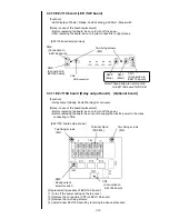
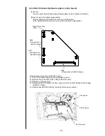
(3) Disconnect the AC input connector of multiple power supply inside the side cover.
(4) Open the maintenance door.
(5) Remove the wire harness from the wire clamp put on the high voltage power supply
protective cover.
(6) Remove the protective cover of high voltage power supply and then remove the
high voltage power supply.
(7) Remove the wire harness from the wire clamp put on the multiple power supply flame.
(8) Remove the fixing screw of back cover.
(9) Remove the two fixing hexagonal spacers and then remove the multiple power supply.
[NOTE] Since the multiple power supply is stuck on the back cover with
double-stick tape, strong power may be needed in the case of removal.
(10)Remove the connector CN2 and 4 of multiple power supply.
(11)Install a new multiple power supply by reversing the above procedure.
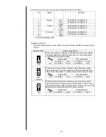
Check the clamping position of wire harness and connection of connectors on EZJ126
board (CN11-14, 20-22, 24).
Ground wire
(Yellow/green
spiral)
Ground wire
(Yellow/green
spiral)
[Inside of side cover]
< RX2-S >
< RX2-B >
EZJ113 board
AC input
connector
[Inside of maintenance cover]
Two fixing hexagonal spacers
EZJ125 board
High voltage
power supply
Multiple power supply
EZJ126 board
Protective cover
of High voltage
power supply
In order to access the
high voltage power
supply, refer to
“3.3.15
high voltage power
supply
”.
With respect to the
clamping position of wire
harness, r
efer to “3.3.18
Electrical connection
diagram
”.
Fixing screw
Содержание IJ RX2
Страница 1: ...Service Manual HITACHI Printer Model RX2 Revision Feb 2014 Version A ...
Страница 13: ...1 8 2 External views Rear side 1 2 2 Main body internal ...
Страница 14: ...1 9 1 2 3 Print head ...
Страница 101: ...3 26 Circuit diagram of EZJ127A ...
Страница 102: ...3 27 Circuit diagram of EZJ127B ...
Страница 116: ...3 41 Circuit diagram of EZJ129 ...
Страница 164: ...4 40 5 Reset the time of the R air filter to 0 on the Parts usage time management screen ...
Страница 247: ...7 Attached Drawing 7 1 Circulation System Diagram Circulation System Diagram 7 1 ...
Страница 248: ...7 2 Electrical Connection Diagram 7 2 1 Electrical Connection Diagram RX2 S Standard model 7 2 ...
Страница 249: ...7 3 7 2 2 Electrical Connection Diagram RX2 B Basic model 7 3 ...
Страница 252: ... Nozzle diameter 65μm 7 6 7 4 Dimensions around charge electrode and deflection electrode 循環系統図 ...


