


3-31
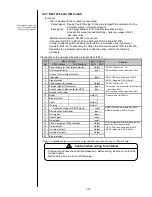
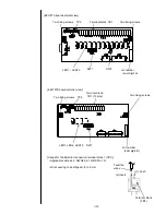
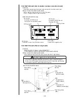
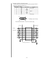
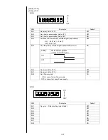
[Connection to the external connection terminal block (EZJ119A -TB2) ]
Pin
N
o
.
Name
Remarks
1
Ready
NC
30VAC/0.5A or 30VDC/1A
2
NO
30VAC/0.5A or 30VDC/1A
3
COM
4
Fault
NC
30VAC/0.5A or 30VDC/1A
5
NO
30VAC/0.5A or 30VDC/1A
6
COM
7
Warning
NC
30VAC/0.5A or 30VDC/1A
8
NO
30VAC/0.5A or 30VDC/1A
9
COM
Terminal specification: M4
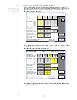
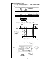
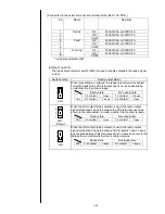
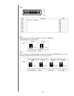
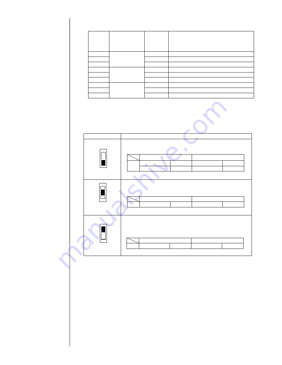
[Setting of switch 3]
The ready output selector switch (SW3) is used to enable or disable the ready signal
output.
Switch setting
Ready output status
When this setting is employed, the ready output signal is enabled.
The path between the TB2 terminals opens or closes depending
on whether the IJ printer is ready.
When the NC contact (break contact) is used, the ready output
signal is disabled. The path between the TB2 terminals opens as
shown in the table below no matter whether the IJ printer is ready.
When the NO contact (make contact) is used, the ready output
signal is disabled. The path between TB2 terminals 1 and 3 opens
and the path between TB2 terminals 2 and 3 closes as shown in the
table below no matter whether the IJ printer is ready.
SW3
3
1
2
SW3
3
1
2
SW3
3
1
2
(
Default
)
Ready state
Not-ready state
TB2
1-3 contact
Open
1-3 contact
Closed
2-3 contact
Closed
2-3 contact
Open
Ready state
Not-ready state
TB2
1-3 contact
Open
1-3 contact
Open
Ready state
Not-ready state
TB2
2-3 contact
Closed
2-3 contact
Closed
Содержание IJ RX2
Страница 1: ...Service Manual HITACHI Printer Model RX2 Revision Feb 2014 Version A ...
Страница 13: ...1 8 2 External views Rear side 1 2 2 Main body internal ...
Страница 14: ...1 9 1 2 3 Print head ...
Страница 101: ...3 26 Circuit diagram of EZJ127A ...
Страница 102: ...3 27 Circuit diagram of EZJ127B ...
Страница 116: ...3 41 Circuit diagram of EZJ129 ...
Страница 164: ...4 40 5 Reset the time of the R air filter to 0 on the Parts usage time management screen ...
Страница 247: ...7 Attached Drawing 7 1 Circulation System Diagram Circulation System Diagram 7 1 ...
Страница 248: ...7 2 Electrical Connection Diagram 7 2 1 Electrical Connection Diagram RX2 S Standard model 7 2 ...
Страница 249: ...7 3 7 2 2 Electrical Connection Diagram RX2 B Basic model 7 3 ...
Страница 252: ... Nozzle diameter 65μm 7 6 7 4 Dimensions around charge electrode and deflection electrode 循環系統図 ...


