Rev. 3.0, 03/01, page 242 of 390
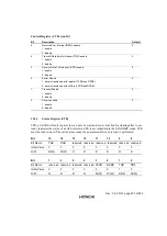
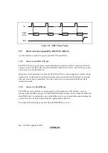
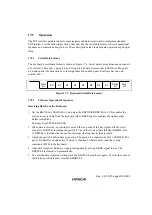
FS
DOUT
(RxD)
data48
data47
data2
data1
RDFI
Figure 15.5 RDFI Output Timing
15.7
How to Use the Special Pin (RLYCNT, RING)
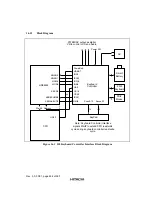
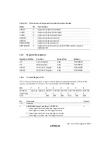
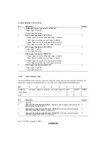
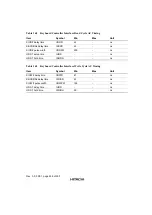
An AFE interface contains two special pins: RLYCNT and RING.
15.7.1
How to use the RLYCNT pin
The RLYCNT pin is used for relay control and dial pulse generation. Relay control is achieved by
writing a value to the RLYCNT bit in CTR while the TSW bit in CTR is 0. A RLYCNT pin output
is the value set in the RLYCNT bit.
Dial pulses can be generated by setting the TSW bit in CTR to 1 and writing data to buffers of data
transmission. At this moment, an Modem interface must be activated and the FS must be accepted
after one word of data is transmitted. The value of the last bit is maintained until the next data
transmission starts.
15.7.2
How to Use the RING pin
The RING pin is used to detect a ringing signal. For this purpose, an AFE interface issues an
interrupt when the RING pin goes low (the RDETM bit must remain at 0). By setting the RSW and
the RDETM bits to 1, reading the value of the RING pin at a receive data buffer and calculating the
cycles of 0 and 1 can be performed while the ringing signal is detected.
Note that a RING interrupt is canceled when the RDETM bit is set to 1.
Содержание HD64465
Страница 25: ...Rev 3 0 03 01 page 6 of 390 ...
Страница 59: ...Rev 3 0 03 01 page 40 of 390 ...
Страница 97: ...Rev 3 0 03 01 page 78 of 390 ...
Страница 147: ...Rev 3 0 03 01 page 128 of 390 ...
Страница 199: ...Rev 3 0 03 01 page 180 of 390 ...
Страница 247: ...Rev 3 0 03 01 page 228 of 390 ...
Страница 385: ...Rev 3 0 03 01 page 366 of 390 ...
Страница 389: ...Rev 3 0 03 01 page 370 of 390 ...
Страница 409: ...Rev 3 0 03 01 page 390 of 390 ...


