Rev. 3.0, 03/01, page 163 of 390
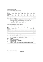
ULCR (READ/WRITE) [cont’d]
Bit
Description
Default
3
Parity Enable (PEN): A parity bit, between the last data word bit and stop bit, will be
generated or checked (transmit or receive data) when ULCR(3) is high.
-
2
Stop Bit Select (STB): Specifies the number of stop bits in each serial character,
summarized as the following:
ULCR(2) Word Length No. of Stop Bits
0 - 1
1 5 bits 1.5
1 6 bits 2
1 7 bits 2
1 8 bits 2
Note: The receiver will ignore all stop bits beyond the first, regardless of the number used
in transmission.
-
1 - 0
Bit 0: Word Length Select Bit 0 (WLS 0): Bit 1: Word Length Select Bit 1 (WLS 1).
Specify the number of bits in each serial character, encoded as the following:
ULCR(1) ULCR(0) Word Length
0 0 5 bits
0 1 6 bits
1 0 7 bits
1 1 8 bits
-
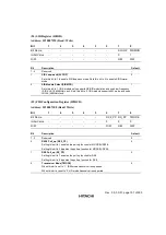
(7) UMCR (READ/WRITE)
Controls the interface with the modem or data set (or device emulating a modem).
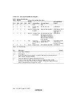
Table 12.4
Modem Control Register Bits
MCR Bits
Logic 1
Logic 0
MCR(7) 0
MCR(6) 0
MCR(5) 0
MCR(4) Loop
MCR(3) Interrupt (INT) Enable
MCR(2) 0
MCR(1) Request to Send (RTS#)
MCR(0) Data Terminal Ready (DTR#)
Loop Enabled
INT Enabled
RTS# Output Low
DTR# Output Low
Loop Disabled
INT Disabled
RTS# Output High
DTR# Output High
Содержание HD64465
Страница 25: ...Rev 3 0 03 01 page 6 of 390 ...
Страница 59: ...Rev 3 0 03 01 page 40 of 390 ...
Страница 97: ...Rev 3 0 03 01 page 78 of 390 ...
Страница 147: ...Rev 3 0 03 01 page 128 of 390 ...
Страница 199: ...Rev 3 0 03 01 page 180 of 390 ...
Страница 247: ...Rev 3 0 03 01 page 228 of 390 ...
Страница 385: ...Rev 3 0 03 01 page 366 of 390 ...
Страница 389: ...Rev 3 0 03 01 page 370 of 390 ...
Страница 409: ...Rev 3 0 03 01 page 390 of 390 ...


