Rev. 3.0, 03/01, page 53 of 390
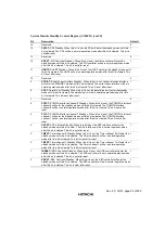
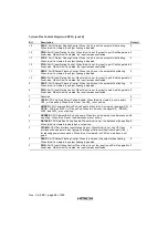
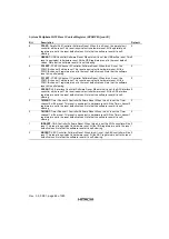
System Module Standby Control Register (SMSCR) [cont’d]
Bit
Description
Default
15
Reserved.
0
14
PS2ST: PS2 Standby. When this bit is set, the PS2 will enter the standby mode until this
bit is cleared. The PS2 will be in normal operation mode after this bit is cleared. This bit is
set after reset.
1
13
Reserved.
0
12
ADCST: A/D Controller Standby. When this bit is set, the A/D controller will enter the
standby mode until this bit is cleared. The A/D controller will be in normal operation mode
after this bit is cleared. This bit is set after reset.
1
11
UARTST: UART Standby. When this bit is set, the UART will enter the standby mode until
this bit is cleared. The UART will be in normal operation mode after this bit is cleared. This
bit is set after reset.
1
10
Reserved
0
9
SCDIST: Serial Codec Interface Standby. When this bit is set, the serial codec interface
will enter the STANDBY mode until this bit is cleared. The serial codec interface will be in
normal operation mode after this bit is cleared. This bit is set after reset.
1
8
PPST: Parallel Port Standby. When this bit is set, the parallel port will enter the standby
mode until this bit is cleared. The parallel port will be in normal operation mode after this
bit is cleared. This bit is set after reset.
1
7
Reserved
0
6
PC0ST: PCMCIA interface Channel 0 Standby. When this bit is set, the PCMCIA interface
channel 0 will enter the standby mode until this bit is cleared. The PCMCIA interface
channel 0 will be in normal operation mode after this bit is cleared. This bit is set after
reset.
1
5
PC1ST: PCMCIA interface Channel 1 Standby. When this bit is set, the PCMCIA interface
channel 1 will enter the standby mode until this bit is cleared. The PCMCIA interface
channel 1 will be in normal operation mode after this bit is cleared. This bit is set after
reset.
1
4
AFEST: AFE interface Standby. When this bit is set, the AFE interface will enter the
standby mode until this bit is clear. The AFE interface will be in normal operation mode
after this bit is cleared. This bit is set after reset.
1
3
TM0ST: Timer channel 0 Standby. When this bit is set, the Timer channel 0 will enter the
standby mode until this bit is cleared. The Timer channel 0 will be in normal operation
mode after this bit is cleared. This bit is clear after reset.
1
2
TM1ST: Timer channel 1 Standby. When this bit is set, the Timer channel 1 will enter the
standby mode until this bit is cleared. The Timer channel 1 will be in normal operation
mode after this bit is cleared. This bit is clear after reset.
1
1
IRDAST: IRDA Controller Standby. When this bit is set, the IrDA controller will enter the
standby mode until this bit is cleared. The IrDA controller will be in normal operation mode
after this bit is cleared. This bit is set after reset.
1
0
KBCST: KBC Controller Standby. When this bit is set, the KBC controller will enter the
standby mode until this bit is cleared. The KBC controller will be in normal operation mode
after this bit is cleared. This bit is clear after reset.
1
Содержание HD64465
Страница 25: ...Rev 3 0 03 01 page 6 of 390 ...
Страница 59: ...Rev 3 0 03 01 page 40 of 390 ...
Страница 97: ...Rev 3 0 03 01 page 78 of 390 ...
Страница 147: ...Rev 3 0 03 01 page 128 of 390 ...
Страница 199: ...Rev 3 0 03 01 page 180 of 390 ...
Страница 247: ...Rev 3 0 03 01 page 228 of 390 ...
Страница 385: ...Rev 3 0 03 01 page 366 of 390 ...
Страница 389: ...Rev 3 0 03 01 page 370 of 390 ...
Страница 409: ...Rev 3 0 03 01 page 390 of 390 ...


