Rev. 3.0, 03/01, page 232 of 390
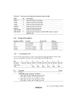
15.2.1
Control Register (CTR)
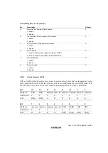
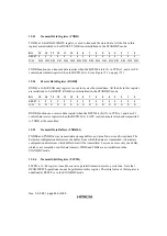
CTR, a 16-bit READ/WRITE register, is used to control an AFE interface. All the bits on this
register are initialized to 0 at RESET. CTR is not initialized in the STANDBY mode.
Bit
15
14
13
12
11
10
9
8
Bit Name
HC
Div2
Div1
RLYCNT CNT2
CNT1
TSW
RSW
Initial Value
0
0
0
0
0
0
0
0
R/W
R/W
R/W
R/W
R/W
R/W
R/W
R/W
R/W
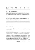
Bit
7
6
5
4
3
2
1
0
Bit Name
RDETM
TEIE
REIE
TXIE
RXIE
BUFD
TE
RE
Initial Value
0
0
0
0
0
0
0
0
R/W
R/W
R/W
R/W
R/W
R/W
R/W
R/W
R/W
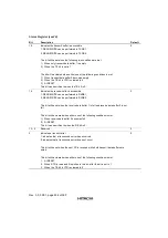
Bit
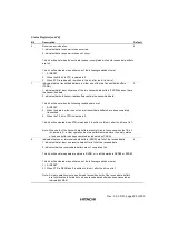
Description
Default
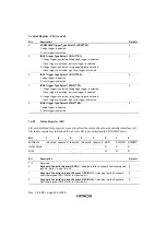
15
When this bit is set to 1, 1 is output from the HC1 pin when the next transmit ends, and
then the value of TXDR is output when the second FS is received. After that, this bit is
cleared to 0.
0
14, 13
Variable M setting for division ratio
00: Division ratio is 1/8
01: Division ratio is 1/7
10: Division ratio is 1/6
11: Reserved
0
12
RLYCNT pin output setting. Output from the RLYCNT pin.
0
11
External control signal 2 (CNT2) setting. Output from the PWRDWNO# pin.
0
10
External control signal 1 (CNT1) setting. Output from the RESETO# Pin.
0
9
RLYCNT pin output switch
1: transmitted data is output from the RLYCNT pin.
0: the value is output, and is set via bit 12 of the RLYCNT pin.
0
8
Receive data input pin switch
1: RING pin input indicates the received data.
0: DOUT (RxD) pin input indicates the received data.
0
7
RDET Interrupt MASK
1: disable
0: enable
0
6
Transmit Error Interrupt (TERI) enable
1: enable
0: disable
0
Содержание HD64465
Страница 25: ...Rev 3 0 03 01 page 6 of 390 ...
Страница 59: ...Rev 3 0 03 01 page 40 of 390 ...
Страница 97: ...Rev 3 0 03 01 page 78 of 390 ...
Страница 147: ...Rev 3 0 03 01 page 128 of 390 ...
Страница 199: ...Rev 3 0 03 01 page 180 of 390 ...
Страница 247: ...Rev 3 0 03 01 page 228 of 390 ...
Страница 385: ...Rev 3 0 03 01 page 366 of 390 ...
Страница 389: ...Rev 3 0 03 01 page 370 of 390 ...
Страница 409: ...Rev 3 0 03 01 page 390 of 390 ...

