80
_____________________________________________________________________________________________
4.4 Trigger Functions
______________________________________________________________________________________________
4.4.5 Channel Trigger
Setting Screen: Trigger
CH1(CH2) (OFF, Level, In, Out, Period)
NOTE
トリガレベル
T
入力波形
【トリガスロープ(
UP
)】
Trigger level
Input waveform
[ Trigger Slope (UP) ]
トリガレベル
T
入力波形
Trigger level
Input waveform
[Trigger Slope (UP)]
[ Trigger Slope (DOWN) ]
A signal input to each channel [CH1, CH2
(Note)
] is used as the trigger
source. (Note) Only CH1 is available with the 8730-10.
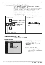
Setting Procedure
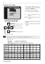
1. Press the
DISPLAY
key and use the right
and left
CURSOR
keys to select the
"
Trigger
" tag.
2
.
Select "
CH1
" or "
CH2
" on the display
menu, then press the
ENTER
key.
3. Using the
CURSOR
key to select an item
to set, then press the
ENTER
key.
The currently selected trigger source is
shown in red.
When the trigger sources are "
OFF
", a
trigger will not be activated.
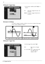
1. Level Trigger (Level, Slope, Filter)
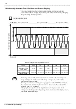
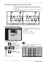
Using the trigger level (voltage), triggering occurs when the input signal
crosses the preset trigger level (voltage) with the preset trigger slope (UP,
DOWN).
The trigger slope (UP, DOWN) is used to select whether a trigger is to be
activated at the rise or fall of an input signal waveform.
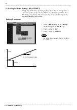
Using the trigger filter prevents an unintended trigger from being activated
by noise.
A trigger will be activated when the trigger conditions are met within the
set filter width.

