66
_____________________________________________________________________________________________
4.3 Details of Input Setting
______________________________________________________________________________________________
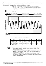
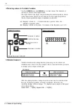
測定可
能範囲(3360
LS
B)
0
-1600 LSB
+1760 LSB
:画面表示範囲
ゼロ位置:0%
ゼロ位置:50%
ゼロ位置:100%
1600
L
S
B
0%
50%
100%
Zero position: 0%
Zero position: 50%
Zero position: 100%
M
ea
su
ra
bl
e
ra
ng
e
: Screen display range
Zoom
X1/2
X1
X2
X5
X10
Number of full
scale LSB
3200
1600
800
320
160
Zero position [%]
setting range
0 to 100
-50 to 150 -150 to 250 -450 to 550 -950 to 1050
NOTE
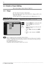
Each range is measurable between -10 times to +11 times the set voltage axis
range. If input exceeds the measurable range, a range-over occurs and the
waveform is shown in black.
If a range-over occurs, a warning message appears and the ERROR terminal (of
the external control terminals) becomes active. You can enable or disable this
function. See 7.5.3 for details.
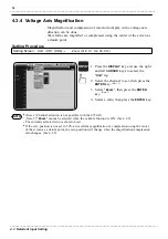
Changing the zero position or the magnification or compression rate of the
voltage axis will change the voltage range shown on the waveform display screen,
but not the measurable range.
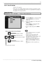
Relationship between Zero Position and Screen Display
The zero position has the following relationship with screen display.
You will be able to display any hidden part of the waveform by changing
the percentage of "0V" position.
When voltage axis magnification is x1


