GE
V
OLUSON
i / V
OLUSON
e
D
IRECTION
KTI106052, R
EVISION
10
S
ERVICE
M
ANUAL
Chapter 3 - Setup Instructions
3-63
3-5-14-2
Voluson i / Voluson e mounted on Modo Cart
NOTE:
For instructions see:
Section 3-5-1-3 "Mounting large Peripherals (e.g., Color Printer)" on page 3-28
.
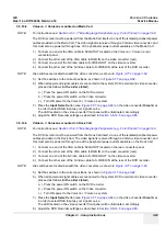
The DVD recorder must be powered from the Modo Cart itself, via one of the isolated peripheral power
cables provided on the Modo Cart. The video signal is received through a VGA-to-video converter, and
this must also be powered through one of the peripheral power outlets available on the Modo Cart.
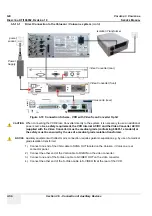
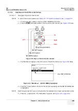
1.) Connect one end of the VGA cable to SVGA OUT located on the Voluson i / Voluson e rear
connector panel.
2.) Connect the other end of the VGA cable to RGB IN on the video converter (rear).
3.) Connect one end of the S-Video cable to S-VIDEO OUT on the video converter.
4.) Connect the other end of the S-Video cable to S-VIDEO IN at the rear of the DVD recorder.
NOTE:
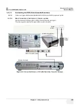
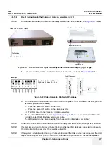
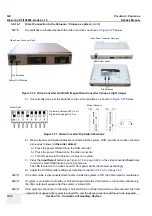
Dip switches are located beneath the video converter, as shown in
Figure 3-77 on page 3-62
.
5.) Set the switches to the correct positions, as shown in
Figure 3-77 on page 3-62
.
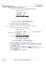
6.) When all power and signal cables are connected to the system, DVD recorder and video converter,
proceed as follows (
in the order stated
):
a.) Press the power ON switch on the DVD recorder.
b.) Press the power ON switch on the Video converter.
c.) Turn ON power to the Voluson i / Voluson e system.
7.) Press the
Input Select
button (see:
Figure 3-77 on page 3-62
) on the video converter
three
times
in order to select RGB Input as your signal source.
The LED located on the video converter front panel will be illuminated, accordingly.
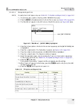
8.) Adjust the DVD Recorder settings as described in
Section 3-5-14-5 on page 3-65
.
3-5-14-3
Voluson i / Voluson e mounted on Dock Cart
NOTE:
For instructions see:
Section 3-5-2-6 "Mounting large Peripherals (e.g., Color Printer)" on page 3-34
.
The DVD recorder must be powered from the Dock Cart itself, via one of the isolated peripheral power
cables provided on the Dock Cart. The video signal is received through a VGA-to-video converter, and
this must also be powered through one of the peripheral power outlets available on the Dock Cart.
1.) Connect one end of the VGA cable to SVGA OUT located on the rear connector panel.
2.) Connect the other end of the VGA cable to RGB IN on the video converter (rear).
3.) Connect one end of the S-Video cable to S-VIDEO OUT on the video converter.
4.) Connect the other end of the S-Video cable to S-VIDEO IN at the rear of the DVD recorder.
NOTE:
Dip switches are located beneath the video converter, as shown in
Figure 3-77 on page 3-62
.
5.) Set the switches to the correct positions, as shown in
Figure 3-77 on page 3-62
.
6.) When all power and signal cables are connected to the system, DVD recorder and video converter,
proceed as follows (
in the order stated
):
a.) Press the power ON switch on the DVD recorder.
b.) Press the power ON switch on the Video converter.
c.) Turn ON power to the Voluson i / Voluson e system.
7.) Press the
Input Select
button (see:
Figure 3-77 on page 3-62
) on the video converter
three
times
in order to select RGB Input as your signal source.
The LED located on the video converter front panel will be illuminated, accordingly.
8.) Adjust the DVD Recorder settings as described in
Section 3-5-14-5 on page 3-65
.
Содержание Voluson i BT06
Страница 2: ......
Страница 11: ...GE VOLUSON i VOLUSON e DIRECTION KTI106052 REVISION 10 SERVICE MANUAL ix ZH CN KO...
Страница 44: ...GE VOLUSON i VOLUSON e DIRECTION KTI106052 REVISION 10 SERVICE MANUAL xlii Table of Contents...
Страница 514: ...GE VOLUSON i VOLUSON e DIRECTION KTI106052 REVISION 10 SERVICE MANUAL IV Index...
Страница 515: ......


